MWO-5-2350-262-35-1 - Page 19 of 24
MWO 5-2350-262-35-1
f.
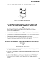
Clean, prime, and paint raw area with suitable CARC prime and finish paint per TB 43-0209.
1.5
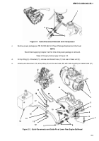
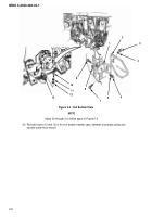
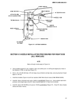
Figure 3-1.
Fire Extinguisher Bottle Holder Shield
SECTION IV. REMOVAL PROCEDURES FOR DRY POWDER (NEW
PRODUCTION VEHICLE SERIAL NUMBERS 574 THROUGH 625)
NOTE
Pay attention to all Notes, Cautions, and Warnings per TM 5-2350-262-20-1, Fixed Dry
Powder Fire Extinguisher Hoses and Fittings Replacement (New Production) and TM 5-2350-
262-20-2, Muffler Shields Replacement.
a.
Remove dry powder fire extinguisher hoses and fittings per TM 5-2350-262-20-1. Remove and discard
four nozzle brackets, nozzles, elbows, and hoses.
b.
Remove dry powder fire extinguisher control valve and cable per TM 5-2350-262-20-1 and TM 5-2350-262-20-
2.
c.
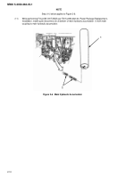
Remove dry powder fire extinguisher cylinder and clamps per TM 5-2350-262-20-1.
d.
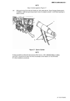
If in like-new condition, re-use dry powder bottles Part Number 14607. Bottles date-stamped five years or
older must be static tested by qualified service facility before reuse is authorized.
SECTION V. NOZZLE INSTALLATION PROCEDURES FOR LEFT SIDE (ALL
VEHICLES)
NOTE
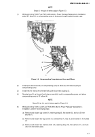
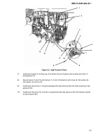
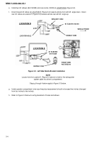
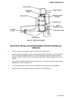
Steps a through f below apply to Figure 3-2.
a.
Using suitable machinist’s ruler, measure, mark, and center punch, for drilling and tapping four holes for
two brackets (10780) on left side (Figure 3-2).
b.
Drill 4 x .25 x 20-UNC-2B holes .375 inch deep only and bottom end tap holes, ensuring maximum thread
depth of .375 inch.
c.
Install two brackets (Figure 3-2) with four washers (MS27183-49) and screws (B1821BH025C050N).
d.
Install one 90˚ elbow (2102-8-8) and nozzle (10250) at LOCATION D (Figure 3-2).
Using suitable
machinist’s protractor and straight edge, direct 90˚ elbow towards engine with 25˚ angle down from
horizontal.
3-3
Back to Top

