MWO-5-2350-262-35-1 - Page 21 of 24
MWO 5-2350-262-35-1
COVER 12476192
HOSE 12476191-2
HOSE 12476191-3
90˚ ELBOW 2102-8-8
SHEATH
K9190606-4-4-4C-30
NOZZLE 10250
CABLE 12481025
ACTUATOR ARM
(Part of assembly 15048)
TEE MS51513A12
BASE PLATE
12476249
STRAIGHT ADAPTER
4FBTX-SS
NOZZLE 10250
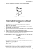
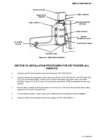
Figure 3-3.
Left Side Installation
45˚ ELBOWS
8-8 140339
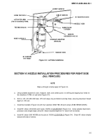
SECTION VI. NOZZLE INSTALLATION PROCEDURES FOR RIGHT SIDE
(ALL VEHICLES)
NOTE
Steps a through e below apply to Figure 3-4.
a.
Using suitable machinist’s ruler, measure, mark, and center punch, for drilling and tapping four holes for
two brackets (10780) on right side (Figure 3-4).
b.
Drill 4 x .25 x 20-UNC-2B holes .375 inch deep only and bottom end tap holes, ensuring maximum thread
depth of .375 inch.
c.
Install two brackets (Figure 3-4) with four washers (MS27183-49) and screws (B1821BH025C050N).
d. Install 90˚ elbow (2102-8-8) and nozzle (10250) at LOCATION F (Figure 3-4).
Using suitable machinist’s
protractor and straight edge, direct 90˚ elbow towards engine at 10˚ down from horizontal.
e. Install 45˚ elbow (8-8 140339) and nozzle at (10250) LOCATION G (Figure 3-4).
Direct 45˚ elbow directly
towards left side of vehicle.
3-5
Back to Top

