MWO-5-2350-262-35-4 - Page 4 of 207
MWO 5--2350--262--35--4
iii
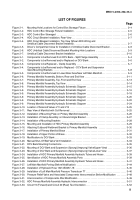
LIST OF FIGURES
Page
Figure 2--1.
Mounting Hole Locations for Control Box Stowage Fixture
2--4
....................................
Figure 2--2.
HDC Control Box Stowage Fixture Installation
2--5
..............................................
Figure 2--3.
HDC Control Box Stowaged
2--6
.............................................................
Figure 2--4.
HDC Circuit Breaker Installation, Rear View
2--7
................................................
Figure 2--4.
HDC Circuit Breaker Installation, Top View (Shown With Wiring and
Umbilical Cable Disconnect Bracket Installed)
2--7
..............................................
Figure 2--5.
Driver’s Compartment Area for Installation of Umbilical Cable Disconnect Bracket
2--8
...............
Figure 2--6.
HDC Umbilical Cable Disconnect Bracket Mounting Hole Locations
2--9
...........................
Figure 2--7.
Umbilical Cable Disconnect Bracket Installation
2--10
............................................
Figure 3--1.
Components to be Removed from DCV Bank -- Split Flange Assembly
3--4
.........................
Figure 3--2.
Components to be Removed and/or Replaced on DCV Bank
3--6
.................................
Figure 3--3.
Components to be Replaced -- Clamp Assembly
3--7
............................................
Figure 3--4.
Components to be Removed and/or Replaced -- DCV Bank and Suspension
Valve Mounting Brackets
3--8
................................................................
Figure 3--5.
Components to be Removed in Lower Bowl Area Near Left Main Manifold
3--9
......................
Figure 3--6.
Primary Manifold Assembly, Bottom, Rear and End View
3--11
....................................
Figure 3--7.
Primary Manifold Assembly, Top, Front and End View
3--13
......................................
Figure 3--8.
Primary Manifold Assembly, Top View
3--14
....................................................
Figure 3--9.
Primary Manifold Assembly Hydraulic Schematic Diagram
3--15
..................................
Figure 3--9.
Primary Manifold Assembly Hydraulic Schematic Diagram
3--16
..................................
Figure 3--9.
Primary Manifold Assembly Hydraulic Schematic Diagram
3--18
..................................
Figure 3--9.
Primary Manifold Assembly Hydraulic Schematic Diagram
3--20
..................................
Figure 3--9.
Primary Manifold Assembly Hydraulic Schematic Diagram
3--22
..................................
Figure 3--9.
Primary Manifold Assembly Hydraulic Schematic Diagram
3--24
..................................
Figure 3--10. Location of Solenoid Valves V11 and V15
3--25
.................................................
Figure 3--11. Rear View of Manifold with Coil Removed
3--25
.................................................
Figure 3--12. Installation of Mounting Plate on Primary Manifold Assembly
3--26
................................
Figure 3--13. Installation of Clamp Assembly on Inbound Angle Bracket
3--27
...................................
Figure 3--14. Installation of Mounting Brackets
3--28
........................................................
Figure 3--15. Mounting and Installation of HDC Primary Manifold Assembly
3--29
...............................
Figure 3--16. Attaching Outboard Weldment Bracket to Primary Manifold Assembly
3--30
........................
Figure 3--17. Installation of Primary Manifold Brace
3--31
....................................................
Figure 3--18. Installation of Upper Portion of Brace
3--32
.....................................................
Figure 3--19. Modifications to DCV Bank
3--33
..............................................................
Figure 3--20. Manual Shut--Off Ball Valve V23 Installation
3--34
...............................................
Figure 3--21. DCV Bank Mounting Connections
3--35
........................................................
Figure 3--22. Mounting of DCV Bank and Suspension (Sprung/Unsprung) Valve/Upper View)
3--36
................
Figure 3--23. Mounting of DCV Bank and Suspension (Sprung/Unsprung) Valve/Lower View
3--37
................
Figure 3--24. Installation of HDC Primary Manifold Assembly Hydraulic Tubes and Hoses
3--39
...................
Figure 3--25. Identification of HDC Primary Manifold Assembly Ports
3--39
.....................................
Figure 3--26. Installation of HDC Primary Manifold Assembly Hydraulic Tubes and Hoses
3--41
...................
Figure 3--27. Left Main Manifold Porting (Before Modification)
3--44
...........................................
Figure 3--28. Installation of Hydraulic Hose 13214E2457--18
3--45
............................................
Figure 3--29. Installation of Left Main Manifold Pressure Transducer T7
3--46
...................................
Figure 3--30. Pressure Relief Valve and Associated Components Interconnection Before Modification
3--48
........
Figure 3--31. Interconnection of Components After Modification
3--49
..........................................
Figure 3--32. HDC Primary Manifold Assembly Hydraulic Interconnection
3--51
.................................
Figure 3--33. Circuit 19 (Forward) and Circuit 20 (Rear) Tee Orientation
3--52
...................................
Back to Top

