MWO-5-2350-262-35-4 - Page 5 of 207
MWO 5--2350--262--35--4
iv
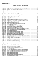
LIST OF FIGURES -- CONTINUED
Page
Figure 3--34. Components to be Removed/Relocated in Main Pump Filter Area
3--53
............................
Figure 3--35. Manual Ball Valve Modification, Right Filter Area
3--55
...........................................
Figure 3--36. Hydraulic Filter Mounting Plates Shown Installed
3--56
..........................................
Figure 3--37. Modifications to Main Pump Right Hydraulic Filter Area (Left Side Shown)
3--58
.....................
Figure 3--38. Manual Ball Valve Modification, Left Filter Area
3--61
............................................
Figure 3--39. Modificaitons to Main Pump Left Hydraulic Filter Area
3--63
......................................
Figure 3--40. Modification to Main Pump Hydraulic Filter Area
3--65
...........................................
Figure 3--41. Valve Components Shown Installed in Support Bracket
3--65
.....................................
Figure 3--42. Installation of Modified Main Pump Hydraulic Filter Assemblies
3--66
..............................
Figure 3--43. Installation of Pressure Transducer T12
3--67
..................................................
Figure 3--44. Location of Access Cover
3--68
...............................................................
Figure 3--45. Modification to Access Cover
3--69
...........................................................
Figure 3--46. Installation of Right Side Bump Stop Cylinder Pressure Transducer T8
3--70
........................
Figure 3--47. Installation of Left Side Bump Stop Cylinder Pressure Transducer T9
3--71
.........................
Figure 3--48. Installation of Pressure Transducer T5
3--72
...................................................
Figure 3--49. Installation of Pressure Transducer T6
3--73
...................................................
Figure 4--1.
Existing Forward Left Manifold Assembly (Being Replaced)
4--4
..................................
Figure 4--2.
Forward Left Manifold Assembly
4--7
..........................................................
Figure 4--3.
Forward Left Manifold Hydraulic Schematic Diagram
4--8
........................................
Figure 4--4.
Installation of New Forward Left Manifold Assembly
4--10
........................................
Figure 4--5.
Identification of Forward Left Manifold Assembly Ports
4--11
......................................
Figure 4--6.
Installation and Interconnection of New Forward Left Manifold Assembly
4--13
......................
Figure 4--7.
Existing Forward Right Manifold Assembly (Being Replaced)
4--14
................................
Figure 4--8.
Forward Right Manifold Assembly
4--16
.......................................................
Figure 4--9.
Forward Right Manifold Hydraulic Schematic Diagram
4--17
......................................
Figure 4--9.
Forward Right Manifold Hydraulic Schematic Diagram
4--18
......................................
Figure 4--10. Installation of New Forward Right Manifold Assembly
4--19
.......................................
Figure 4--11. Identification of Forward Right Manifold Assembly Ports
4--20
....................................
Figure 4--12. Installation and Interconnection of New Forward Right Manifold Assembly
4--22
.....................
Figure 4--13. Aft Manifold Assembly
4--25
.................................................................
Figure 4--14. Aft Manifold Hydraulic Schematic Diagram
4--26
................................................
Figure 4--15. Mounting and Installation of Aft Manifold on 1” (2.54 cm) Thick Hull
4--28
...........................
Figure 4--16. Interconnection of Aft Manifold Assembly on 1” Thick Hull Bottom
4--30
............................
Figure 4--17. Identification of Aft Manifold Assembly Ports
4--30
..............................................
Figure 5--1.
Initial Placement of Upper Cable Assembly W2
5--3
.............................................
Figure 5--2.
Cable Connector Installation Orientation (Typical)
5--4
...........................................
Figure 5--3.
Typical Cable Connector Installation
5--5
......................................................
Figure 5--3.
Typical Cable Connector Installation
5--6
......................................................
Figure 5--4.
Placement of Upper Cable Assembly W2
5--7
..................................................
Figure 5--5.
Initial Placement of Lower Cable Assembly W3
5--9
.............................................
Figure 5--6.
Initial Routing of Power Cable Assembly W1
5--10
..............................................
Figure 5--7.
Connection of HDC Power Distribution Components
5--11
.......................................
Figure 5--8.
Parking Brake Relay Terminals
5--12
..........................................................
Figure 5--9.
HDC Power Cable Assembly W1 Connection to Parking Brake Relay
5--13
.........................
Figure 5--10. Routing of Cable Assembly W1 Branch 1069 From Disconnect Bracket
5--14
.......................
Figure 5--11. Routing of Cable Assembly W1 Branch 1069 to Compartment Wall
5--15
...........................
Figure 5--12. Upper Cable Assembly W2 Routing
5--17
......................................................
Figure 5--12. Upper Cable Assembly W2 Routing
5--20
......................................................
Figure 5--13. Electrical Connections on Primary Manifold Assembly
5--21
......................................
Figure 5--14. Lower Cable Assembly W3 Routing
5--22
......................................................
Back to Top

