MWO-5-2350-262-35-4 - Page 6 of 207
MWO 5--2350--262--35--4
v
LIST OF FIGURES -- CONTINUED
Page
Figure 5--15. Electrical Connections on Forward Left Manifold Assembly
5--25
..................................
Figure 5--16. Electrical Connections on Forward Right Manifold Assembly
5--25
................................
Figure 5--17. Electrical Connections on Aft Manifold Assembly
5--26
..........................................
Figure 5--18. Access Cover Location
5--28
.................................................................
Figure 5--19. HDC Control Box
5--29
......................................................................
Figure 5--20. Umbilical Cable Assembly W4 Connection to Umbilical Cable Disconnect Bracket
5--30
..............
Figure 5--21. Umbilical Cable Assembly W4 Connections to HDC Control Box
5--30
.............................
Figure B--1.
Dimensional Drawing for Fabricating Wheel Support Wedge
B--1
.................................
Figure B--2.
Dimensional Drawing for Fabricating Ejector Cylinder Mount Spacer Plate
B--2
....................
Figure B--3.
Right and Left Side Wheel Support Wedge Locations
B--3
.......................................
Figure B--4.
Wheel Support Wedge Welded in Position
B--4
................................................
Figure B--5.
Ejector Cylinder Bracket Removal
B--5
.......................................................
Figure B--6.
Spacer Block Installed
B--6
.................................................................
LIST OF TABLES
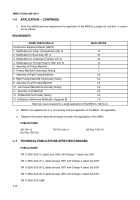
Table 1--1.
Driver’s Compartment Modification Kit Parts List
1--3
............................................
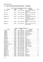
Table 1--1.
Driver’s Compartment Modification Kit Parts List -- Continued
1--3
.................................
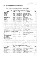
Table 1--2.
Bowl Area Modification Kit Parts List
1--3
......................................................
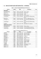
Table 1--2.
Bowl Area Modification Kit Parts List -- Continued
1--4
...........................................
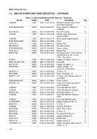
Table 1--2.
Bowl Area Modification Kit Parts List -- Continued
1--5
...........................................
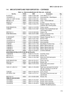
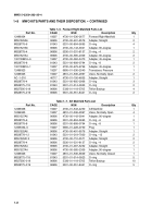
Table 1--2.
Bowl Area Modification Kit Parts List -- Continued
1--6
...........................................
Table 1--3.
Primary Manifold Parts List
1--6
..............................................................
Table 1--4.
Vehicle Underside Modification Kit Parts List
1--7
...............................................
Table 1--5.
Forward Left Manifold Parts List
1--7
..........................................................
Table 1--6.
Forward Right Manifold Parts List
1--8
.........................................................
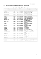
Table 1--7.
Aft Manifold Parts List
1--8
...................................................................
Table 1--8.
Electrical Modification Kit Parts List
1--9
.......................................................
Table 1--9.
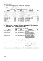
Bulk and Expendable Material Modification Kit Parts List
1--10
....................................
Table 1--10.
Common Tools Required
1--10
...............................................................
Table 1--11.
Special Tools Required
1--10
.................................................................
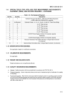
Table 1--12.
Test Equipment Required
1--11
...............................................................
Table 3--1.
HDC Primary Manifold Assembly Hydraulic Connections
3--42
....................................
Table 3--1.
HDC Primary Manifold Assembly Hydraulic Connections -- Continued
3--43
........................
Table 4--1.
Interconnection of New Forward Left Manifold Assembly Hydraulic Hoses and Tubes
4--12
...........
Table 4--2.
Interconnection of New Forward Right Manifold Assembly Hydraulic Hoses and Tubes
4--21
..........
Table 4--3.
Interconnection of Aft Manifold Assembly Hydraulic Hoses
4--31
..................................
Table 5--1.
Upper Cable Assembly W2 Electrical Connections
5--18
.........................................
Table 5--1.
Upper Cable Assembly W2 Electrical Connections -- Continued
5--19
..............................
Table 5--2.
Lower Cable Assembly W3 Electrical Connections
5--23
.........................................
Table 5--2.
Lower Cable Assembly W3 Electrical Connections -- Continued
5--24
..............................
Table B--1
Hull/Ejector Interference Modification Parts List
LIST OF FOLDOUTS
FO 3--1
M9 ACE HDC Hydraulic Schematic (Sheet 1 of 3)
FP--1
.........................................
FO 3--1
M9 ACE HDC Hydraulic Schematic (Sheet 2 of 3)
FP--3
.........................................
FO 3--1
M9 ACE HDC Hydraulic Schematic (Sheet 3 of 3)
FP--5
.........................................
FO 3--2
Filter Area -- Front Compartment Plate Modifications
FP--7
......................................
FO 4--1
Mounting the Aft Manifold
FP--9
..............................................................
Back to Top

