MWO-9-2320-273-20-1 - Page 16 of 28
MWO 9-2320-273-20-1
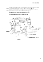
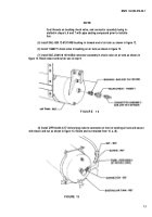
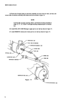
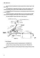
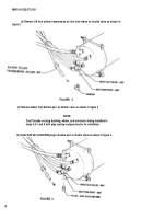
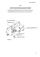
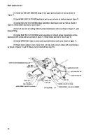
(15) Cut off one inch of existing 5/8-inch yellow transmission airline as shown in figure 16, and
discard fitting.
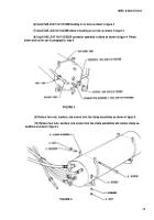
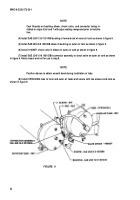
(16) Install SAE J246 10-10100101BA union assembly on 5/8-inch yellow transmission air line
and secure with sleeve and nut as shown in figure 16. Retain sleeve and nut for use within step 17.
(17) Install CPR104420-4 (53 inches long) tube on union assembly and secure with sleeve and nut
as shown in figure 16.
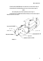
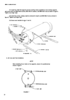
(18) Route tube through two clamps and to elbow in rear of air tank, and install tube on elbow
and secure with nut and sleeve as shown in figure 15 and 16. Sleeve and nut retained from step (14).
(19) Install two MS3367-7-9 straps around airlines as shown in figure 16.
FIGURE 16
c. Vehicle Equipment.
(1) Start vehicle and build air pressure up to operating range (refer to TM 9-2320-273-10).
(2) Inspect vehicle for air leaks, loose fittings, screws, and nuts (refer to TM 9-2320-273-10).
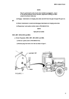
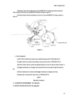
(3) Shut off vehicle and drain air system by opening draincock on existing air tank only as shown
in figure 14.
16
Back to Top

