MWO-9-2330-390-35-1 - Page 11 of 48
MWO 9-2330-390-35-1
11
person reporting the MWO data, will acquire the remaining elements (3 &
5), and input all nine into MMIS.
DATA Elements
Input Data
1.
Material Change Number (MCN)
2.
MWO Number
3.
Unit Identification Code (UIC) @ Battalion Level
4.
NSN of End Item
5.
Serial Number
6.
USA Registration Number
7.
Date of Application
8.
Hours required for Application.
9.
Software Version
(3)
For off-line reporting, the 3.5-inch disk shall be mailed to the following
address:
Commander
TACOM-Warren
ATTN: AMSTA-LC-CIPWM
Warren, MI 48397-5000
b.
Marking Equipment.
(1) After the Positioning Tube Reinforcement Kit is installed, mark MWO
under 9-2330-390-35-1 in the MWO Applied block and Date Applied in
Date Block on MWO instruction plate P/N 10930014 (91).
(2)
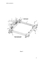
To install the MWO instruction plate, locate and drill a 0.082-0.086
inch
diameter hole on the front upper left (hydraulic valve side) vertical tube
above the instruction plate (see figure 11). Use #4-3/16 drive screws to
attach.
15.
MATERIAL CHANGE (MC) NUMBER.
a. The Material Change (MC) Number for this MWO is 1-02-08-0001
16.
MODIFICATION IDENTIFICATION.
a.
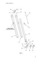
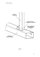
When installed correctly, the Positioning Tube Reinforcement Kit will appear as
shown in figure 10.
b.
After the Positioning Tube Reinforcement Kit is installed, the positioning tube
reinforcement should be inspected for secure mounting. Any faults detected, or
discrepancies noted, will be corrected before the dolly is returned to normal
service.
Back to Top

