MWO-9-2330-390-35-1 - Page 8 of 48
MWO 9-2330-390-35-1
8
of torque, insure that each of the steel bushings (23) fit into the holes in each
tab of the tube mount.
6.
Torque lower tube connection bolts (22) to 25-30 ft-lbs.
7.
Repeat steps 2 though 7 to complete second lower tube connection.
8.
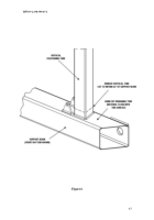
Slide one of the upper vertical tubes (34 or 35) over an assembled lower
vertical tube.
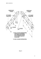
Proper assembly will have the stability cable mount positioned
inboard and to the container mounting surface as shown in Figure 9.
9.
Per Figure 9, insert clevis pin (29) into upper vertical tube (34 or 35), tube
mounting tabs on the upper beam (1), and the positioning cylinder rod end (2).
10.
Add spacer (31) to free end of clevis pin (29).
11.
Insert cotter pin (30) to complete upper tube connection.
12.
Repeat steps 9 though 12 to complete second upper tube connection.
13.
Install both stability cables (27) to mounts provided as shown in Figure 9
14.
Install instruction plates previously removed (Task 17, Appendix C, Section a)
on front dolly upper vertical tube. Use plate as template to drill 6 (0.082-
0.086) holes for mounting plate. Position first plate (uncoupling instructions)
25” below upper beam on front upper left (hydraulic valve side) vertical tube.
Position second plate (coupling instructions) ½” below the first plate. Use #4-
3/16 drive screws to attach.
15.
Install hanger brackets (front dolly). Position previously removed hanger
bracket on upper vertical tube (34), 8 in (15.2cm) below top beam (1).
Reinstall U-bolt, and two flat washers with new locknuts.
d.
Installation
NOTE
•
Installation procedures are the same for the front and rear dollies.
Figure
10 illustrates installation for the front dolly.
1.
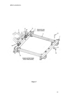
Install the assembled structural frame to both the front and rear dollies (Figure
10) (Refer to Appendix C, Section c).
This includes the bottom beams if
removed.
NOTE
•
Prior to operation of the modified Dolly set, properly check hydraulic
system for leaks and bleed (Refer to Appendix D).
2.
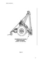
Remove wooden blocks (12”x12” stock) under each end of each bottom beam
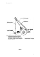
and place dolly half into maneuvering position (Figure 3) (Refer to Appendix B,
Section a).
3.
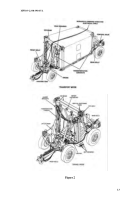
Perform operations needed to return dollies to travel or transport mode Figure 2.
11.
CALIBRATION REQUIREMANTS.
Not applicable to this MWO
Back to Top

