MWO-9-2330-390-35-1 - Page 7 of 48
MWO 9-2330-390-35-1
7
NOTE
•
Steps 3 through 6 describe the modification of the support beams.
Accurate
component identification and placement is essential to proper installation.
•
All welding should adhere to procedures in accordance with AWS D1.1.
Surfaces to be welded must be preheated for proper fusion.
Weld filler material
to be 70 Ksi min tensile strength.
Weld joints should be metal to metal fit.
Weld gaps shall not exceed 0.09 inch.
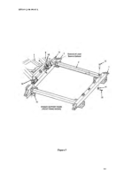
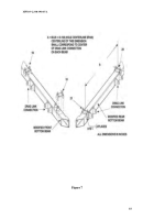
3.
Position tube mounts (19) over the front bottom beam as designated in Figure
7.
Clamp and weld in place.
4.
Position tube mounts (20 & 21) over the rear bottom beam as designated in
Figure 7.
Clamp and weld in place.
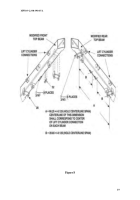
5.
Position tube mounts (28) over the front and rear top beams as designated in
Figure 8.
Clamp and weld in place.
6.
Position stability cable mounts (32) on front and rear top beams as designated
in Figure 8.
Clamp and weld in place.
7.
Perform visual and Dye penetrant inspection of welds per AWS D1.1. Dye
penetrant inspection shall only be performed on suspect welds.
8.
Once modified, clean, treat, prime and CARC topcoat in accordance with
MIL-C-53072 (ME) and drawing 12355846.
Effected area modified must be
sanded to ‘White Metal’, re-primed using Moisture-Cure Zinc rich primer in
accordance with drawing 12461890, 1.5 mil min dry film thickness and top
coated in accordance with 12355846-100.
c.
FRAME ASSEMBLY
NOTE
•
Assembly procedures are the same for the front and rear dollies.
Figure
9 illustrates assembly for the front dolly.
•
Mounting hardware must face outward to prevent interference.
1.
Attach cylinder shims (25) to tube mounts on bottom beam (3) using flat head
screws (26).
Torque each screw to 10 ft-lbs.
2.
Position mounting tabs on lower vertical tube (33) between the tube mount
tabs on the bottom beam.
3.
Insert the positioning cylinder (2) into the lower vertical tube (33) with the
hydraulic connections facing outboard as shown in Figure 9.
4.
Insert bolt (22) through one steel bushing (23) with bushing shoulder adjacent
to bolt head.
Per Figure 9, insert bolt and bushing sub-assembly through the
tube mounting tabs on the bottom beam, the lower vertical tube (34) and the
positioning cylinder base (2).
5.
Place a second steel bushing (23) onto bolt (22).
Finish the lower tube
connection by placing locking nut (24) onto bolt (22).
Prior to the application
Back to Top

