MWO-9-2330-390-35-1 - Page 6 of 48
MWO 9-2330-390-35-1
6
3.
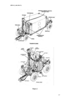
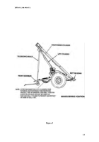
Place front and rear dollies into maneuvering position (Figure 3) and separate
by a distance of at least 30 ft or side by side. (Refer to Appendix B, Section a).
4.
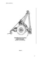
Place wooden blocks (12”x12” stock) under each end of each bottom beam
and remove dolly half from maneuvering position (Refer to Appendix B,
Section b).
The condition of each dolly half should resemble Figure 4.
NOTE
•
Removal of the top hooks, detent lanyard pins, and toolbox-mounting
brackets (front dolly) is not necessary.
5.
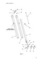
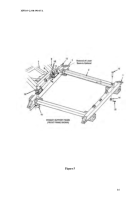
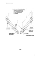
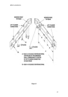
Remove the top and bottom beams and positioning cylinders from both the
front and rear dollies (Figure 5) (Refer to Appendix C, Section a).
NOTE
•
The preferred method of applying the MWO is performing the required
cutting, grinding, welding and painting WITHOUT removing bottom dolly
beams from dolly suspension (see Figure 5). The bottom beams of the
dolly may be removed from the dolly suspension if required IAW TM 9-
2330-390-14&P.
However extreme care must be taken during reassemble
due to close tolerances.
6.
With a permanent-marking device, appropriately identify each support beam
for future reference (i.e. front bottom, front top, rear bottom, or rear top).
7.
Clean and inspect all parts (Refer to Appendix C, Section b).
b.
TOP AND BOTTOM BEAM PREPARATION
NOTE
•
Preparation procedures are NOT the same for the front and rear or the
top and bottom beams.
Discrepancies will be noted when necessary.
•
All surfaces to be welded should be free of paint and other surface
treatments.
Three recommended methods for removal are the use of
plastic media blasting at approximately 40 PSI, the use of paint remover
such as MIL-R-81294, type I, or the use of a hand-held portable
sander/grinder equipped with a wire brush.
1.
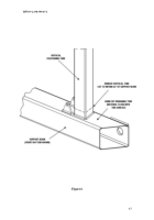
Remove the vertical tubes from the top and bottom beams obtained from both
the front and rear dolly. Cut tubes within 0.5 in. from each support beam
surface (Figure 6).
2.
Grind off remaining tube material flush with surface of beam at all vertical
tube connections.
Back to Top

