TB-9-2320-279-13-P-2 - Page 309 of 460
II106700-5
Rev. B
Page 45
m.
Apply Loctite 242 to five bolts (3/8 – 16 x 1.500 LG).
n.
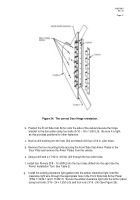
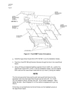
Secure the Upper Brush Guard (P/N 111407-1) to the HEMTT using five bolts
(3/8 – 16 x 1.500 LG) and washers (3/8 ID) (See Figure 28) on the upper portion of
the Brush Guard, removing the two Installation Guides (P/N 107430-1) as the bolts
are installed.
Hand-tighten the bolts.
Remove the material handling equipment and
lift sling from the Upper Brush Guard.
p.
Adjust and position the Upper and Lower Brush Guards as necessary until the
desired position is achieved, and then install 9 bolts (3/8 – 16 x 1.250 LG),
18 flat washers (3/8 ID), and 9 locknuts (3/8 – 16) through the Upper and Lower
Brush Guard mating point, between the headlight cutouts.
Hand-tighten the nuts.
r.
Verify the proper positioning of the Lower Brush Guard (P/N 111496-1) and the bolt
holes at the bottom edge of the Lower Brush Guard under the cab door.
s.
Torque the eight bolts (3/8 – 16 x 1.500 LG), on the Lower Brush Guard sides to
23 ft-lb.
t.
Torque the five bolts (3/8 – 16 x 1.500 LG), on the uppermost portion of the Upper
Brush Guard to 23 ft-lb.
u.
Torque the nine locknuts and bolts (3/8 – 16 x 1.500 LG), in the bolt line even with
the headlight cutouts, to 35 ft-lb.
v.
Install the Upper Brush Guard Cover (P/N 111437-1) using three bolts
(3/8 – 16 x 1.500 LG), six washers (3/8 ID), and three locknuts (3/8 – 16).
(Note:
The notched portion is up when the vehicle does not have a gun ring mount.)
Back to Top

