TB-9-2320-280-35-12 - Page 118 of 162
TB 9-2320-280-35-12
5-90
Section XLV. DRIVER-SIDE MULTI-NET RACK CABLE INSTALLATION
45-1.
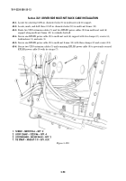
Locate two existing 0.281-in. diameter holes (8) in multi-net rack (6) support.
45-2.
Locate, mark, and drill three 0.147-in. diameter holes (10) in multi-net frame (11).
45-3.
Route two URO extension cables (5) and two EPLRS power cables (9) from multi-net rack (6)
support along multi-net frame (11) to curbside footwell.
45-4.
Secure one EPLRS power cable (9) to multi-net rack (6) support with two clamps (2), screws (4),
lockwashers (3), and nuts (1).
45-5.
Secure one EPLRS power cable (9) to multi-net frame (11) with three clamps (2) and screws (12).
45-6.
Secure two URO extension cables (5) and remaining EPLRS power cable (9) to previously secured
EPLRS power cable (9) with tie straps (7).
1
2
3
4
5
6
7
8
9
~
Figure 5-129.
1. SCREW – MS90725-6 – QTY. 2
2. LOOP CLAMP – 3225T46 – QTY. 4
3. LOCKWASHER – MS35338-44 – QTY. 2
7. TIE STRAP – MS3367-1-0 – QTY. A/R
Back to Top


