TB-9-2320-302-13-P-2 - Page 111 of 396
TB 9-2320-302-13&P-2
REAR CAB ARMOR REPLACEMENT - CONTINUED
0018 00
0018 00-5
INSTALLATION - CONTINUED
3.
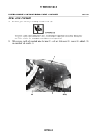
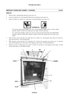
Install two rear grab handles with adapter plates (17), eight washers (16), new lockwashers (15), and nuts (14) on rear
cab armor frame (11).
WARNING
•
Use extreme caution when handling heavy parts. Provide adequate support and use assistance during
procedure. Failure to follow this warning may cause injury or death to personnel.
•
For proper threat protection, armor must be installed correctly into the armor frame. During installation,
ensure that the surface marked “STRIKE FACE” is facing outward towards the threat. Exposing the
passive side of the ballistic panel outward makes the armor less effective. Failure to follow this warning
may cause injury or death to personnel.
4.
With assistance, install three bottom rear cab armor panels (13) into rear cab armor frame (11).
5.
Install three center support dividers (12) into rear cab armor frame (11).
6.
With assistance, install two top rear cab armor panels (9) into rear cab armor frame (11).
7.
Install emergency egress panel (10) (WP 0019 00).
8.
Install two brackets (5), four washers (4), new lockwashers (3), and bolts (2) on rear cab armor frame (11).
9.
Install two rear cab lights (1) with two washers (7), new lockwashers (8), and nuts (6) on rear cab armor frame (11).
440-089
2,3,4
1
9
10
11
12
13
14,15,16
17
5
6,7,8
Back to Top


