TB-9-2320-302-13-P-2 - Page 254 of 396
ArmorWorks
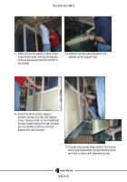
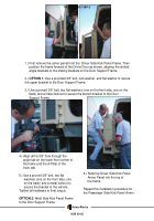
4.) Align drill a 3/8” hole through the
angle tab on the lower-front corner of
the frame and the A-Pillar of the
truck cab.
5.) Use a proved 3/8” bolt, two flat
washers (one on the front side, one
on the back) and a metal locknut to
secure the bracket to the vehicle.
Tighten all hardware to final torque.
OPTION 2:
Weld Side Kick Panel Frame
to the Door Support Frame.
1.) First remove the armor panel from the
Driver Side Kick Panel Frame. Then
position the frame forward of the Driver Door as shown, aligning the slotted
angle brackets to the mating brackets on the Door Support Frame.
2.)
OPTION 1:
Use a provided 3/8” bolt, lock washer, and flat washer to secure
the upper bracket to the Door Support Frame.
3.) Use a proved 3/8” bolt, two flat washers (one on the front side, one on the
back) and a metal locknut to secure the bottom bracket to the Door
Support Frame.
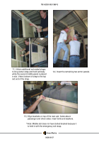
6.) Slide the Driver Side Kick Panel
Armor Panel into the top of
the frame.
Repeat this installation procedure for
the Passenger Side Kick Panel Armor.
TB 9-2320-302-13&P-2
0038 00-42
Back to Top

