TB-9-2320-302-13-P-2 - Page 310 of 396
TSB 011 – Door Cam Latch Installation (Continued)
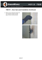
4. Now that the centers of the “V”
notches have been located, mark the
cutouts by tracing the Alignment
Angles, PN 110-170361-001.
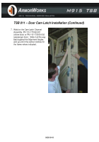
Hold
the part flush to the inside surface of
the door frame by holding it against a
flat plate as shown.
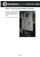
5. Cutout the four rectangular and “V”
notches using the Sawzall and cutoff
wheel.
0039 00-16
Back to Top


