TB-9-2320-302-13-P-2 - Page 313 of 396
TSB 011 – Door Cam Latch Installation (Continued)
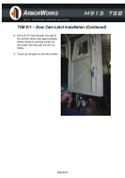
8. Drill a 5/16” hole through one wall of
the bottom frame tube approximately
where shown to provide a drain for
any water that may get into the cut
frame.
9. Touch-up the paint on the door frame.
0039 00-19
Back to Top

