TB-9-2320-302-13-P-2 - Page 307 of 396
TSB 0011 - Heavy–Duty Door Cam Latch Assembly
20 Dec 2005
REQUIRED TOOLS:
Welder
5/16” Drill Bit and Drill
1/2” Wrench and Ratchet
7/16” Ratchet
Phillips Head Screwdriver
Touchup Paint
Sawzall or Metal Cutting Wheel
PROCEDURE:
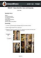
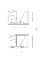
1. Cut two “V” grooves and two rectangular cuts in door frame as shown.
2. Weld in Angle Guides P/N 110-170361-001
3. Weld Door Cam Latch Assembly P/N 110-170360-001/2 to armor door frame (001
is driver side 002
is passenger.
“V” Grooves
Rectangular
Cuts
0039 00-13
Back to Top


