TB-9-2320-302-13-P-3 - Page 74 of 240
TB 9-2320-302-13&P-3
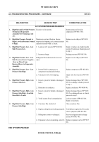
A/C TROUBLESHOOTING PROCEDURES - CONTINUED
0013 00
0013 00-10
A/C ELECTRICAL SYSTEM - CONTINUED
2.
A/C System Energized But
Evaporator Assembly Does Not
Function - Continued.
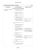
(b) Set A/C fan switch to the OFF
position (WP 0004 00).
(c) Remove black wire connector from
evaporator blower assembly (WP
0017 00).
(d) Disconnect black wire connector
from blower motor assembly (WP
0017 00).
(e) Check continuity between black
wire terminal on connector to
evaporator blower assembly and
black wire terminal on wire
disconnected from blower motor
(wire from dome light connector).
1. If continuity is not indicated,
repair or replace black wire.
2. If continuity is indicated, proceed
to next step.
(f) Return equipment to normal
condition.
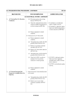
10. Verify power circuit to blower motor.
(a) Connect black wire connector from
evaporator blower assembly (WP
0017 00).
(b) Disconnect orange wire connector
from blower motor assembly (WP
0017 00).
(c) Turn ignition key switch to the ON
position (TM 9-2320-363-10).
(d) Set A/C fan switch to the ON
position (WP 0004 00).
(e) Check for 24 VDC on orange wire
terminal of wire disconnected from
blower motor to black wire
connector disconnected from
blower motor assembly (wire from
dome light connector).
1. If 24 VDC is indicated, replace
blower motor.
2. If 24 VDC is not indicated, replace
orange wire.
(f) Return equipment to normal
condition.
MALFUNCTION
TEST OR INSPECTION
CORRECTIVE ACTION
Back to Top


