TB-9-2320-302-13-P-3 - Page 77 of 240
TB 9-2320-302-13&P-3
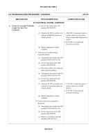
A/C TROUBLESHOOTING PROCEDURES - CONTINUED
0013 00
0013 00-13
A/C ELECTRICAL SYSTEM - CONTINUED
4.
Evaporator Assembly Works But
Compressor Does Not -
Continued.
(a) Turn ignition key switch to the OFF
position (TM 9-2320-363-10).
(b) Set A/C fan switch to the OFF
position (WP 0004 00).
(c) Disconnect diode harness from
chassis harness (WP 0019 00).
(d) Disconnect diode harness from
compressor clutch connector (WP
0019 00).
(e) Check for continuity between green
wire terminal of diode harness
(positive lead of meter) and vehicle
ground (negative lead of meter).
1. If continuity is indicated (less then
1 Meg Ohm), replace diode.
2. If continuity is not indicated
(greater then 1 Meg Ohm),
proceed to next step.
(f) Return equipment to normal
condition.
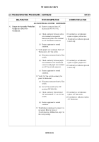
5. Check high pressure switch on receiver/
dryer for proper operation.
(a) Turn ignition key switch to the OFF
position (TM 9-2320-363-10).
(b) Set A/C fan switch to the OFF
position (WP 0004 00).
(c) Disconnect wiring connector at
high pressure switch on receiver/
dryer (yellow and green wires) (WP
0019 00).
(d) Install jumper wire across high
pressure switch connector.
(e) Start engine (TM 9-2320-363-10).
(f) Set A/C fan switch to the ON
position (WP 0004 00).
(g) Verify compressor clutch engages. 1. If compressor clutch does not
engage, proceed to step 7.
2. If compressor clutch engages,
proceed to next step.
(h) Return equipment to normal
condition.
MALFUNCTION
TEST OR INSPECTION
CORRECTIVE ACTION
Back to Top

