TB-9-2320-302-13-P-3 - Page 75 of 240
TB 9-2320-302-13&P-3
A/C TROUBLESHOOTING PROCEDURES - CONTINUED
0013 00
0013 00-11
A/C ELECTRICAL SYSTEM - CONTINUED
3.
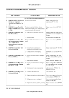
Evaporator Assembly Works But
Engine Fan Does Not.
1. Verify operation of engine fan pressure
switch on receiver/dryer.
(a) Start engine (TM 9-2320-363-10).
(b) Set A/C fan switch to the ON
position (WP 0004 00).
(c) Disconnect engine fan pressure
switch connector on receiver/dryer
(connector with purple and red
wires) (WP 0019 00).
(d) Install jumper wire across engine
fan switch connector.
(e) Verify engine fan operation.
1. If engine fan does not operate,
proceed to step 3.
2. If engine fan operates, proceed to
next step.
2. Verify A/C system pressures (WP 0015
00).
1. If system is operating within
normal parameters, replace
pressure switch (WP 0019 00).
2. If system is not operating within
normal parameters, inspect system
for leaks (WP 0015 00).
3. Verify continuity on purple wire to
engine fan pressure switch.
(a) Turn ignition key switch to the OFF
position (TM 9-2320-363-10).
(b) Set A/C fan switch to the OFF
position (WP 0004 00).
(c) Disconnect engine fan pressure
switch connector on receiver/dryer
(connector with purple and red
wires) (WP 0019 00).
(d) Disconnect purple wire from
engine coolant temperature switch
(WP 0018 00).
(e) Check continuity from purple wire
terminal on engine fan pressure
switch and purple wire terminal
removed from engine coolant
temperature switch.
1. If continuity is not indicated,
repair or replace purple wire.
2. If continuity is indicated, repair or
replace red wire.
MALFUNCTION
TEST OR INSPECTION
CORRECTIVE ACTION
Back to Top

