TB-9-2320-335-13-P - Page 278 of 680
TB 9-2320-335-13&P
10-16
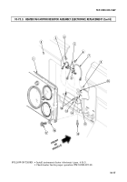
10-75.3. HEATER FAN MOTOR RESISTOR ASSEMBLY (ELECTRONIC) REPLACEMENT
This task covers:
a. Removal
b. Installation
Tools
General mechanic’s tool kit:
automotive (Appendix B, Item 1)
Manual References
TM 9-2320-387-10
TB 9-2320-335-13&P, Appendix E
Equipment Condition
Instrument cluster (electronic) removed
(para. 4-14.1).
Maintenance Level
Unit
INITIAL SETUP:
1.
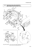
Remove four capscrews (17), washers (16), and instrument cluster (1) from instrument panel (2).
2.
Remove two nuts (4) and (6) and resistor (8) from threaded studs (12) on instrument panel (2).
NOTE
Prior to removal, tag leads for installation.
3.
Disconnect harness lead 399 (3) from harness lead 399A (11).
4.
Disconnect harness lead 400 (5) from harness lead 400D (10).
5.
Disconnect harness lead 400 (7) from harness lead 400A (9).
6.
Remove nut (14), capscrew (15), and resistor plate (13) from instrument panel (2).
1.
Install resistor plate (13) on instrument panel (2) with capscrew (15) and nut (14).
2.
Connect harness lead 400 (7) to harness lead 400A (9).
3.
Connect harness lead 400 (5) to harness lead 400D (10).
4.
Connect harness lead 399 (3) to harness lead 399A (11).
5.
Install resistor (8) on threaded studs (12) on instrument panel (2) with two nuts (4) and (6).
6.
Install instrument cluster (1) on instrument panel (2) with four capscrews (17) and washers (16).
b. Installation
a. Removal
Back to Top

