TB-9-2920-225-34-1 - Page 3 of 70
TB 9-2920-225-34-1
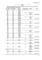
Figure
2–7
2-8
2-9
2-10
2-11
2-12
2-13
2-14
2-15
2-16
2-17
2-18
2-19
2–20
2-21
2-22
2-23
3-1
3–2
3-3
3–4
3-5
3-6
3-7
3-8
3-9
3-10
3-11
3-12
3-13
3-14
3-15
4-1
4-2
4-3
5-1
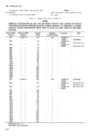
Table
2-1
2-2
2-3
2-4
2-5
2-6
2-7
2-8
2-9
2-10
3-1
3-2
3–3
3-4
3-5
3-6
4-1
Title
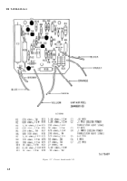
Circuit board—model 03_ _ _ _ _ _ _ _ _ _ _ _ _ _ _ _ _ _ _ _ _ _ _ _ _ _ _
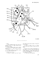
Test points–model 03___________________________________________________________
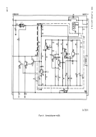
Schematic diagram—model 03______________________________________________________
Vap-Air
model
26440001-04______________________________________________________________
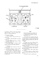
End view—model
04____________________________________________________________________
Diode mounting—model
04________________________________________________________________
Relay location—model
04_________________________________________________________________
Circuit board and transistor heat sink-model
04___________________________________________________
Test points—model 04_________________________________________________________
Schematic diagram—model
04_____________________________________________________________
Vap-Air model 26440001-05 ______________________________________________________________
End view—model 05 _____________________________________________________________________
Diode mounting—model 05________________________________________________________________
Relay location—model 05 _________________________________________________________________
Circuit board and transistor heat sink—model 05 ________________________________________________
Test
Points-model
05_____________________________________________________________________
Schematic diagram—mode1
05_____________________________________________________________
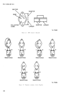
NPN transistor (Leece-Neville)______________________________________________________________
Transistor resistance checks (Leece-Neville)____________________________________________________
Top view (Leece-Neville)—model 5027RA____________________________________________________
Circuit
board—model
5027RA_____________________________________________________________
Schematic diagram—mode1 5027RA_________________________________________________
Leece-Neville model 5027RB exploded view___________________________________________________
Openview—mode15027RB____________________________________________________________
Leece-Neville model 5027RC exploded view_________________________________________________
Openview—mode15027RC______________________________________________________
Circuit
board—mode15027RC______________________________________________________________
Schematic diagram—mode1
5027RC_____________________________________________
Leece-Neville
mode15027RD______________________________________________________________
Circuit board removed—mode1 5027RD_____________________________________________________
Test points-model 5027RD ________________________________________________________________
Schematic
diagram—mode15027RD_________________________________________________________
NPN transistor (Leland Airborne Model)_______________________________________________________
Transistor resistance checks (Leland Airborne Model) ____________________________________________
Schematic diagram, circuit board, and bracket assy (Leland Airborne model)_____________________________
100 AMP solid state regulator checker_________________________________________________________
LIST OF TABLES
Title
Replacement Parts List-Model 01___________________________________________________________
Resistance Checks (Power-off)-Model 03_____________________________________________________
Voltage Checks (Power on)—Mode103_____________________________________________
Substitutes for Diode D1–Model 03________________________________________________________
Resistance Checks (Power otO—Mode104____________________________________________________
Voltage Checks (Power on)—Mode1 04_______________________________________________________
Substitutes for transistor Q5-Model 04________________________________________________________
Resistance Checks(Power off)–Model 05_______________________________________________________
VoltageChecks (Power on)—Mode1 05___________________________________________________
Substitutes for transistor Q5—Model 05____________________________________________________
Resistance Checks (Power off)-Mode15027RA________________________________________________
Voltage Checks (Power on)—Mode15027RA___________________ _
Resistance Checks (Power off)—Mode15027RC________________________________________
Voltage Checks (Power on)—Mode15027RC__________________ _
Resistance Checks (Power off) —Mode15027RD_________________________________________________
Substitutes for Diode Z1-Model 5027RD_______________________ _
Replacement Parts List-Leland Airborne Model_ _ _ _ _ _ _ _ _ _ _ _ _ _ _ _ _ _ _ _ _
Page
2-8
2-9
2-10
2-14
2-15
2-17
2-18
2-19
2-20
2-21
2-23
2-24
2-25
2-26
2-27
2-28
2-29
3-2
3-2
3-3
3-4
3-5
3-8
3-9
3-10
3-11
3-12
3-13
3-16
3-18
3-19
3-20
4-2
4-2
4-3
5-2
Page
2-3
2-11
2-12
2-18
2-15
2-16
2-18
2-30
3-30
2-31
3-6
3-14
3-14
3-17
3-17
4-4
3-6
ii
Back to Top

