TB-9-3950-253-13-P
PALLETIZED LOAD SYSTEM TRUCK, M1075 and M1075A1 (PLS) AND HEAVY EXPANDED MOBILITY TACTICAL TRUCK, M1120, M1120A2, AND M1120A4 (HEMTT), ENHANCED CONTAINER HANDLING UNIT (E-CHU)
TECHNICAL BULLETIN; OPERATOR AND FIELD MAINTENANCE, INSTALLATION INSTRUCTIONS, AND REPAIR PARTS AND SPECIAL TOOLS LIST
JULY 2009
TB-9-3950-253-13-P - Page 264 of 704
0025-2
TB 9-3950-253-13&P
0025
REMOVAL
00025
WARNING
During these procedures, the operator will be required to climb on and around the vehicle.
Be sure to wear suitable footwear and that no surfaces are slippery. Wear suitable gloves
and hard hat. Failure to follow this warning may result in injury to personnel.
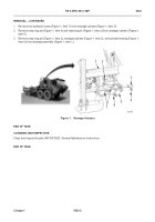
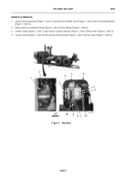
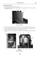
1. Remove three locknuts (Figure 1, Item 19), washers (Figure 1, Item 20), bolts (Figure 1, Item 1), washers
(Figure 1, Item 2), and sensor cover (Figure 1, Item 3) from stowage assembly (Figure 1, Item 21). Discard
locknuts.
NOTE
Note placement of sensor arm on sensor linkage to aid in installation.
2. Remove locknut (
Figure 1,
Item 8), washer (
Figure 1,
Item 7), bolt (
Figure 1,
Item 15), washer (
Figure 1,
Item
14), and sensor arm (
Figure 1,
Item 6) from sensor linkage (
Figure 1,
Item 13). Discard locknut.
3. Remove locknut (
Figure 1,
Item 5), washer (
Figure 1,
Item 4), and sensor arm (
Figure 1,
Item 6) from stowage
guide (
Figure 1,
Item 22). Discard locknut.
4. Remove two locknuts (
Figure 1,
Item 10), washers (
Figure 1,
Item 11), bolts (
Figure 1,
Item 18), washers
(
Figure 1,
Item 17), and angle sensor (
Figure 1,
Item 9) from sensor bracket (
Figure 1,
Item 16). Discard
locknuts.
5. Disconnect harness (
Figure 1,
Item 12) from angle sensor (
Figure 1,
Item 9).
END OF TASK
CLEANING AND INSPECTION
00025
Clean and inspect all parts IAW WP 0020,
General Maintenance Instructions
.
END OF TASK
INSTALLATION
00025
WARNING
During these procedures, the operator will be required to climb on and around the vehicle.
Be sure to wear suitable footwear and that no surfaces are slippery. Wear suitable gloves
and hard hat. Failure to follow this warning may result in injury to personnel.
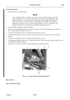
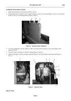
1. Connect harness (Figure 1,
Item 12) to angle sensor (
Figure 1,
Item 9).
2. Install angle sensor (
Figure 1,
Item 9), two washers (
Figure 1,
Item 17), bolts (
Figure 1,
Item 18), washers
(
Figure 1,
Item 11), and new locknuts (
Figure 1,
Item 10) on sensor bracket (
Figure 1,
Item 16).
Back to Top

