TB-9-3950-253-13-P
PALLETIZED LOAD SYSTEM TRUCK, M1075 and M1075A1 (PLS) AND HEAVY EXPANDED MOBILITY TACTICAL TRUCK, M1120, M1120A2, AND M1120A4 (HEMTT), ENHANCED CONTAINER HANDLING UNIT (E-CHU)
TECHNICAL BULLETIN; OPERATOR AND FIELD MAINTENANCE, INSTALLATION INSTRUCTIONS, AND REPAIR PARTS AND SPECIAL TOOLS LIST
JULY 2009
TB-9-3950-253-13-P - Page 256 of 704
TB 9-3950-253-13&P
Change 1
0023-4
0023
FOLLOW-ON TASKS
00023
1. Stow lift frame on vehicle (WP 0007).
NOTE
When stowing lift frame, if lift frame lower securing tube is positioned above and to the
front of stowage rack lock bracket, the cylinder rod end may need adjustment. This
adjustment will move the stop position of the capture frame rearward, causing the lift
frame securing tube to move rearward and downward. The cylinder rod end may be
adjusted to a maximum of 3/8 in. out from original position. A 1/8 in. adjustment in the
cylinder rod end will move the lift frame securing tube approximately 1/4 in.
2. Unload lift frame and place on ground (
WP 0007
).
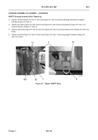
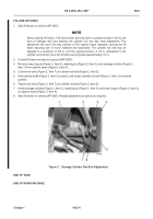
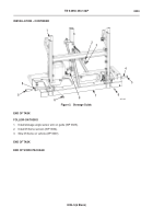
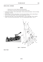
3. Remove snap ring pin (Figure 2, Item 6), retaining pin (Figure 2, Item 5), and stowage cylinder (Figure 2,
Item 1) from capture frame (Figure 2, Item 4).
4. Loosen two bolts (Figure 2, Item 7) on cylinder rod end (Figure 2, Item 3).
5. Hold cylinder shaft (Figure 2, Item 2) in place, and loosen cylinder rod end (Figure 2, Item 3) to desired
position.
6. Tighten two bolts (Figure 2, Item 7) on cylinder rod end (Figure 2, Item 3).
7. Install stowage cylinder (Figure 2, Item 1), retaining pin (Figure 2, Item 5), and snap ring pin (Figure 2, Item 6),
on capture frame (Figure 2, Item 4).
8. Stow lift frame on vehicle (
WP 0007
). Repeat adjustment procedure as required.
Figure 2.
Stowage Cylinder Rod End Adjustment.
023
END OF TASK
END OF WORK PACKAGE
Back to Top

