TB-9-3950-253-13-P
PALLETIZED LOAD SYSTEM TRUCK, M1075 and M1075A1 (PLS) AND HEAVY EXPANDED MOBILITY TACTICAL TRUCK, M1120, M1120A2, AND M1120A4 (HEMTT), ENHANCED CONTAINER HANDLING UNIT (E-CHU)
TECHNICAL BULLETIN; OPERATOR AND FIELD MAINTENANCE, INSTALLATION INSTRUCTIONS, AND REPAIR PARTS AND SPECIAL TOOLS LIST
JULY 2009
TB-9-3950-253-13-P - Page 308 of 704
TB 9-3950-253-13&P
Change 1
0029-26
0029
INSTALLATION – CONTINUED
Valve Harness Installation
00029
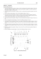
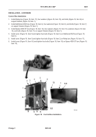
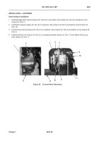
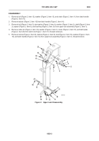
1. Install stowage latch harness (Figure 22, Item 8) on pneumatic valve (Figure 22, Item 6) and tighten screw
(Figure 22, Item 7).
2. Install stow harness (
Figure 22,
Item 9) on hydraulic valve (
Figure 22,
Item 5) and tighten screw (
Figure 22,
Item 10).
3. Install unstow harness (
Figure 22,
Item 3) on hydraulic valve (
Figure 22,
Item 5) and tighten screw (
Figure 22,
Item 4).
4. Install manifold cover (
Figure 22,
Item 2) on stowage assembly (
Figure 22,
Item 11) and tighten three wing
bolts (
Figure 22,
Item 1).
Figure 22.
Connect Valve Harnesses.
0029
467-232
3
1
2
9
7,8
11
11
5
10
4
6
Back to Top

