TB-9-3950-253-13-P
PALLETIZED LOAD SYSTEM TRUCK, M1075 and M1075A1 (PLS) AND HEAVY EXPANDED MOBILITY TACTICAL TRUCK, M1120, M1120A2, AND M1120A4 (HEMTT), ENHANCED CONTAINER HANDLING UNIT (E-CHU)
TECHNICAL BULLETIN; OPERATOR AND FIELD MAINTENANCE, INSTALLATION INSTRUCTIONS, AND REPAIR PARTS AND SPECIAL TOOLS LIST
JULY 2009
TB-9-3950-253-13-P - Page 313 of 704
0029-31/(32 Blank)
Change 1
TB 9-3950-253-13&P
0029
INSTALLATION – CONTINUED
Twistlock Sensor Harness Installation – Continued
00029
NOTE
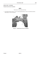
Perform step 2 for both right and left sides.
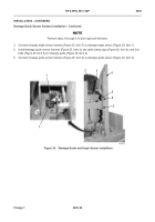
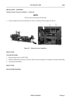
2. Connect twistlock sensor harness (Figure 28, Item 1) to twistlock sensor (Figure 28, Item 2).
Figure 28.
Twistlock Sensor Installation.
0029
END OF TASK
FOLLOW-ON TASKS
00029
1. Install stowage control unit (
WP 0045
).
2.
Calibrate middle frame and hook arm sensors. Refer to
Sensor Calibration
in
Installation Instructions
(WP 0052).
3. Load lift frame (WP 0007).
END OF TASK
END OF WORK PACKAGE
1
2
Back to Top

