TB-9-3950-253-13-P
PALLETIZED LOAD SYSTEM TRUCK, M1075 and M1075A1 (PLS) AND HEAVY EXPANDED MOBILITY TACTICAL TRUCK, M1120, M1120A2, AND M1120A4 (HEMTT), ENHANCED CONTAINER HANDLING UNIT (E-CHU)
TECHNICAL BULLETIN; OPERATOR AND FIELD MAINTENANCE, INSTALLATION INSTRUCTIONS, AND REPAIR PARTS AND SPECIAL TOOLS LIST
JULY 2009
TB-9-3950-253-13-P - Page 320 of 704
TB 9-3950-253-13&P
0030-6
0030
INSTALLATION
00030
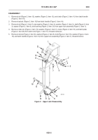
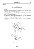
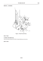
1. Install plate (Figure 5, Item 8), two washers (Figure 5, Item 9), bolts (Figure 5, Item 10), washers (Figure 5,
Item 7), and new locknuts (Figure 5, Item 6) on lift frame (Figure 5, Item 1).
WARNING
•
Lifting cables, chains, hooks, and slings used for lifting must be in good condition and of
suitable capacity.
•
Improper use of lifting equipment and improper attachment of cables may cause injury to
personnel and damage to equipment. Observe all standard rules of safety.
•
Use extreme caution when handling heavy parts. Provide adequate support and use
assistance during procedure. Ensure any lifting device used is in good condition and of
suitable load capacity. Keep clear of heavy parts supported only by lifting device.
•
Failure to follow these warnings may result in injury or death to personnel.
NOTE
•
Upper lock assembly weighs 90 lb (41 kg).
•
Perform these procedures for both right and left sides.
•
Install upper lock assembly on lift frame as noted during removal.
2.
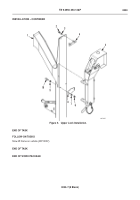
Attach sling and lifting device to upper lock assembly
(Figure 1, Item 5).
3. Use lifting device to install upper lock assembly (Figure 5, Item 5) on lift frame (Figure 5, Item 1).
4. Install stop block (Figure 5, Item 4), two washers (Figure 5, Item 3), and new locknuts (Figure 5, Item 2) on lift
frame (Figure 5, Item 1).
5. Remove lifting device and sling from upper lock assembly (Figure 5, Item 5).
Back to Top


