TB-9-3950-253-13-P
PALLETIZED LOAD SYSTEM TRUCK, M1075 and M1075A1 (PLS) AND HEAVY EXPANDED MOBILITY TACTICAL TRUCK, M1120, M1120A2, AND M1120A4 (HEMTT), ENHANCED CONTAINER HANDLING UNIT (E-CHU)
TECHNICAL BULLETIN; OPERATOR AND FIELD MAINTENANCE, INSTALLATION INSTRUCTIONS, AND REPAIR PARTS AND SPECIAL TOOLS LIST
JULY 2009
TB-9-3950-253-13-P - Page 319 of 704
0030-5
TB 9-3950-253-13&P
0030
ASSEMBLY
00030
NOTE
Install latch rod as noted during removal.
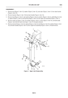
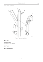
1. Install latch rod (Figure 3, Item 1) and nut (Figure 3, Item 2) on adjustment bar (Figure 3, Item 3) keeping rod
ends parallel.
2.
Install latch handle (Figure 3, Item 6), bolt (Figure 3, Item 5), washer (Figure 3, Item 4), washer (Figure 3, Item 7),
and new locknut (Figure 3, Item 8) on adjustment bar (Figure 3, Item 3).
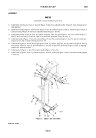
3. Install latch handle (Figure 4, Item 14), washer (Figure 4, Item 15), bolt (Figure 4, Item 16), washer (Figure 4,
Item 8), and new locknut (Figure 4, Item 9) in upper lock assembly (Figure 4, Item 1).
4. Install latch plate (Figure 4, Item 20), clevis (Figure 4, Item 18), washer (Figure 4, Item 7), and new cotter pin
(Figure 4, Item 19) on latch rod (Figure 4, Item 17).
5. Install shaft (Figure 4, Item 2), bushing (Figure 4, Item 21), spacer (Figure 4, Item 6), washer (Figure 4, Item 3),
star washer (Figure 4, Item 4), and bolt (Figure 4, Item 5) on upper lock assembly (Figure 4, Item 1) aligning
spacer with opening in shaft.
6. Install keylock (Figure 4, Item 10) in latch handle (Figure 4, Item 14).
7. Install chain (Figure 4, Item 11), washer (Figure 4, Item 13), and bolt (Figure 4, Item 12) on latch handle (Figure
4, Item 14).
Figure 4.
Upper Lock Assembly.
030
END OF TASK
2
1
17
3
4
5
7
9
8
10
12
13
14
15
16
18
19
20
11
21
6
Back to Top

