TB-9-3950-253-13-P
PALLETIZED LOAD SYSTEM TRUCK, M1075 and M1075A1 (PLS) AND HEAVY EXPANDED MOBILITY TACTICAL TRUCK, M1120, M1120A2, AND M1120A4 (HEMTT), ENHANCED CONTAINER HANDLING UNIT (E-CHU)
TECHNICAL BULLETIN; OPERATOR AND FIELD MAINTENANCE, INSTALLATION INSTRUCTIONS, AND REPAIR PARTS AND SPECIAL TOOLS LIST
JULY 2009
TB-9-3950-253-13-P - Page 344 of 704
0034-8
TB 9-3950-253-13&P
0034
TWISTLOCK SENSOR INSTALLATION
00034
1.
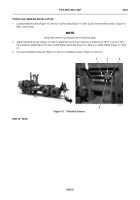
Loosely install two bolts (Figure 10, Item 4) in cable clamp (Figure 10, Item 2) and insert twistlock sensor (Figure 10,
Item 3) into clamp.
NOTE
Verify that sensor is perpendicular to twistlock plate.
2. Adjust twistlock sensor (Figure 10, Item 3) placement until end of sensor is 0.0625 to 0.1875 in. (2 to 3 mm)
from twistlock plate (Figure 10, Item 4) and tighten two bolts (Figure 10, Item 4) in cable clamp (Figure 10, Item
2).
3. Connect electrical connector (Figure 10, Item 1) to twistlock sensor (Figure 10, Item 3).
Figure 10.
Twistlock Sensor.
0034
END OF TASK
4
1
2
3
Back to Top


