TB-9-3950-253-13-P
PALLETIZED LOAD SYSTEM TRUCK, M1075 and M1075A1 (PLS) AND HEAVY EXPANDED MOBILITY TACTICAL TRUCK, M1120, M1120A2, AND M1120A4 (HEMTT), ENHANCED CONTAINER HANDLING UNIT (E-CHU)
TECHNICAL BULLETIN; OPERATOR AND FIELD MAINTENANCE, INSTALLATION INSTRUCTIONS, AND REPAIR PARTS AND SPECIAL TOOLS LIST
JULY 2009
TB-9-3950-253-13-P - Page 348 of 704
TB 9-3950-253-13&P
0034-12
0034
HOOK ARM SENSOR INSTALLATION – CONTINUED
4. Shut off vehicle and set ignition switch to ON position
(PLS: TM 9-2320-364-14&P, HEMTT: TM 9-2320-326-
14&P).
NOTE
Ensure stowage control toggle switch is set to OFF position.
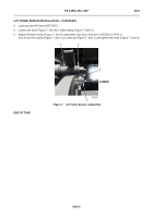
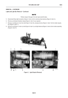
5. Adjust nut (Figure 16, Item 4) until face of sensor is 0.0625 to 0.1875 in. (2 to 3 mm) from sensor plate (Figure
16, Item 6).
6. Slide hook arm sensor (Figure 16, Item 2) on bracket (Figure 16, Item 3) toward sensor plate (Figure 16,
Item 6) and identify position where sensor light (Figure 16, Item 1) turns on. Tighten nut (Figure 16, Item 5) at
that position.
7. Return hook arm to stowed position (PLS: TM 9-2320-364-14&P, HEMTT: TM 9-2320-326-14&P).
Figure 16.
Hook Arm Sensor Calibration.
0034
END OF TASK
END OF WORK PACKAGE
3
2
1
4
5
6
Back to Top


