TB-9-3950-253-13-P
PALLETIZED LOAD SYSTEM TRUCK, M1075 and M1075A1 (PLS) AND HEAVY EXPANDED MOBILITY TACTICAL TRUCK, M1120, M1120A2, AND M1120A4 (HEMTT), ENHANCED CONTAINER HANDLING UNIT (E-CHU)
TECHNICAL BULLETIN; OPERATOR AND FIELD MAINTENANCE, INSTALLATION INSTRUCTIONS, AND REPAIR PARTS AND SPECIAL TOOLS LIST
JULY 2009
TB-9-3950-253-13-P - Page 435 of 704
0045-9/(10 Blank)
Change 1
TB 9-3950-253-13&P
0045
INSTALLATION – CONTINUED
NOTE
•
Route and install wires and harnesses as tagged during removal.
•
Install new tiedown straps as required.
1.
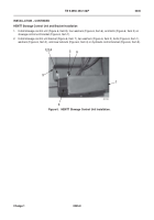
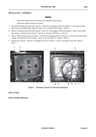
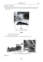
Route RH twistlock wiring harness (Figure 7, Item 9) into stowage control unit (Figure 7, Item 3) and install
blue, brown, and black wires (Figure 7, Item 7) on connector P10 (Figure 7, Item 6).
2.
Route LH twistlock wiring harness (Figure 7, Item 10) into stowage control unit (Figure 7, Item 3) and install
blue, brown, and black wires
(
Figure 7
, Item 4)
on connector P9 (Figure 7, Item 5).
3.
Route CAN bus wiring harness (Figure 7, Item 8) into stowage control unit (Figure 7, Item 3) and install yellow,
orange, red and brown wires (Figure 7, Item 11) on connector P1 (Figure 7, Item 12).
4.
Install cover (Figure 7, Item 2) on stowage control unit (Figure 7, Item 3) and tighten four bolts (Figure 7,
Item 1).
Figure 7.
Stowage Control Unit Harness Installation.
045
END OF TASK
END OF WORK PACKAGE
467-224
4
5
6
9
8
10
12
2
1
3
7
11
Back to Top


