TB-9-3950-253-13-P
PALLETIZED LOAD SYSTEM TRUCK, M1075 and M1075A1 (PLS) AND HEAVY EXPANDED MOBILITY TACTICAL TRUCK, M1120, M1120A2, AND M1120A4 (HEMTT), ENHANCED CONTAINER HANDLING UNIT (E-CHU)
TECHNICAL BULLETIN; OPERATOR AND FIELD MAINTENANCE, INSTALLATION INSTRUCTIONS, AND REPAIR PARTS AND SPECIAL TOOLS LIST
JULY 2009
TB-9-3950-253-13-P - Page 441 of 704
0046-5
TB 9-3950-253-13&P
0046
CALIBRATION – CONTINUED
7. Set battery disconnect switch and ignition switch to ON position (PLS: TM 9-2320-364-14&P, HEMTT: TM 9-
2320-326-14&P).
NOTE
Value should be approximately 15 mA when stowage guide is vertical and approximately 4
mA when guide is tilted fully toward rear.
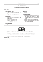
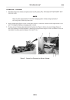
8. Move stowage guide (Figure 5, Item 1) and watch values on multimeter. Values should range between 4 mA
and 15 mA (approximately) as stowage guide is moved.
9. If values are out of range, adjust placement of sensor arm (Figure 5, Item 2) on sensor linkage (Figure 5,
Item 4) by installing mounting hardware in different mounting locations (Figure 5, Item 3). Measure current at
new location to ensure value is between 4 mA and 15 mA.
Figure 5.
Sensor Arm Placement on Sensor Linkage.
046
2
1
3
4
5
Back to Top

