TB-9-3950-253-13-P
PALLETIZED LOAD SYSTEM TRUCK, M1075 and M1075A1 (PLS) AND HEAVY EXPANDED MOBILITY TACTICAL TRUCK, M1120, M1120A2, AND M1120A4 (HEMTT), ENHANCED CONTAINER HANDLING UNIT (E-CHU)
TECHNICAL BULLETIN; OPERATOR AND FIELD MAINTENANCE, INSTALLATION INSTRUCTIONS, AND REPAIR PARTS AND SPECIAL TOOLS LIST
JULY 2009
TB-9-3950-253-13-P - Page 442 of 704
TB 9-3950-253-13&P
0046-6
0046
CALIBRATION – CONTINUED
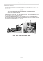
10. When calibration is complete, install sensor cover (
Figure 6,
Item 1), three bolts (
Figure 6,
Item 5), washers
(
Figure 6,
Item 6), washers (
Figure 6,
Item 3), and new locknuts (
Figure 6,
Item 4) on stowage assembly
(
Figure 6,
Item 2).
Figure 6.
Sensor Cover Installation.
046
NOTE
•
Install hoses as tagged during removal.
•
Remove caps prior to installation.
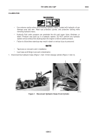
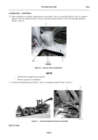
11. Connect two hydraulic hoses (Figure 7, Item 1) to stowage cylinder (Figure 7, Item 2).
Figure 7.
Connect Hydraulic Hoses to Cylinder.
046
END OF TASK
1
2
5, 6
3, 4
(HIDDEN)
Insert Art # 467-322
2
1
Back to Top


