TB-9-3950-253-13-P
PALLETIZED LOAD SYSTEM TRUCK, M1075 and M1075A1 (PLS) AND HEAVY EXPANDED MOBILITY TACTICAL TRUCK, M1120, M1120A2, AND M1120A4 (HEMTT), ENHANCED CONTAINER HANDLING UNIT (E-CHU)
TECHNICAL BULLETIN; OPERATOR AND FIELD MAINTENANCE, INSTALLATION INSTRUCTIONS, AND REPAIR PARTS AND SPECIAL TOOLS LIST
JULY 2009
TB-9-3950-253-13-P - Page 433 of 704
0045-7
Change 1
TB 9-3950-253-13&P
0045
INSTALLATION
0045
WARNING
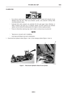
During these procedures, the operator will be required to climb on and around the vehicle.
Be sure to wear suitable footwear and that no surfaces are slippery. Wear suitable gloves
and hard hat. Failure to follow this warning may result in injury to personnel.
NOTE
•
Perform steps 1 and 2 for PLS M1075 trucks.
•
Perform steps 3 thru 5 for PLS M1075A1 trucks.
PLS Stowage Control Unit and Bracket Installation
00045
1.
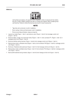
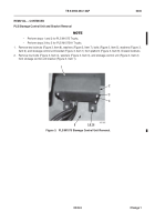
Install stowage control unit (Figure 5, Item 2), four washers (Figure 5, Item 3), and bolts (Figure 5, Item 4) on
stowage control unit bracket (Figure 5, Item 1).
2.
Install stowage control unit bracket (
Figure 5
, Item 1), two washers (
Figure 5
, Item 6), bolts (
Figure 5
, Item 5),
washers (
Figure 5
, Item 7), and new locknuts (
Figure 5
, Item 8) on platform (
Figure 5
, Item 9).
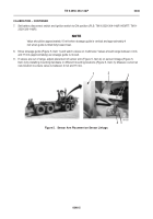
Figure 5.
PLS M1075 Stowage Control Unit Installation.
045
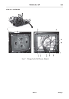
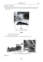
3.
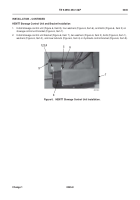
Install bracket (Figure 4, Item 11), four washers (Figure 4, Item 10), bolts (Figure 4, Item 9), washers (Figure 4,
Item 8), and new locknuts (Figure 4, Item 7) on fender (Figure 4, Item 12).
4.
Install backplate (Figure 4, Item 2), two washers (Figure 4, Item 4), bolts (Figure 4, Item 3), washers (Figure 4,
Item 5), and new locknuts (Figure 4, Item 6) on bracket (Figure 4, Item 11).
5.
Install stowage control unit (Figure 4, Item 1) and four bolts (Figure 4, Item 13) on backplate (Figure 4, Item 2).
2
9
1
3
4
5,6,7,8
Back to Top

