TM-3-1040-279-12-P - Page 27 of 389
TM 3-1040-279-12&P
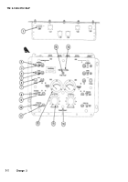
2-2 CONTROL PANEL ASSEMBLY
KEY
1
2
3
4
5
6
7
8
9
1 0
1 1
1 2
1 3
1 4
1 5
1 6
CONTROL OR INDICATOR
Circuit Breaker (CB1)
POWER On/Off Switch
POWER Indicator
FUEL Switch
FUEL Indicator
AIR PURGE Switch
AIR Indicator
ENGINE Switch
ENGINE Indicator
FOG OIL Switch
FOG OIL Indicator
SMOKE TEMP Indicator
FOG OIL FLOW Knob
PANEL LIGHT Control Knob
Fire Warning Indicator
FIRE TEST Switch
FUNCTION
Disconnects power source from system when an electrical
malfunction occurs.
Supplies power to the control circuits for the corresponding
smoke generator.
Indicates that power is supplied to the system control circuits.
Press to test function checks the lamp in the indicator.
Supplies power to the corresponding fuel pump to obtain
operating pressure in the START position and the continuous
operation in the RUN position.
Indicates sufficient fuel pressure is available for operating the
system. The press to test function checks the lamp in the
indicator.
Used to purge pulse jet engine.
Indicates when sufficient air pressure is present to start or
purge the pulse jet engines. Press to test function checks the
lamp in the indicator.
Provides ignition, starting air, and fuel to the corresponding
pulse jet engine in the START position then fuel for continuous
operation in the RUN position.
Indicates when the pulse jet engine is capable of operating on
its own. Press to test function checks the lamp in the indicator.
Supplies power to the corresponding fog oil pump to obtain
operating pressure in START position and continuous operation
in the RUN position.
Indicates when sufficient fog oil pressure is obtained for opera-
tion. Press to test function checks the lamp in the indicator.
Monitors the temperature of the corresponding pulse jet engine.
Regulates the flow of fog oil supplied to the corresponding
pulse jet engine.
Varies the brightness of the panel lights.
Indicates the prescence of a fire in one or both of the smoke
generators.
Checks proper operation of the fire detection system. Both
generators must be electrically connected for system to
operate.
Change 3
2-3
Back to Top

