TM-5-2330-325-13-P - Page 210 of 648
RECEPTACLE REPAIR
1.
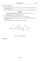
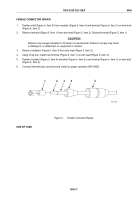
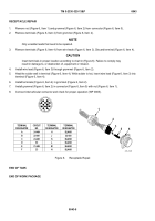
Remove nut (Figure 6, Item 1) and grommet (Figure 6, Item 2) from connector (Figure 6, Item 5).
2.
Remove terminals (Figure 6, Item 4) from grommet (Figure 6, Item 2).
NOTE
Only unsolder leads that need to be repaired.
3.
Remove terminals (Figure 6, Item 4) from wire leads (Figure 6, Item 3). Discard terminal (Figure 6, Item 4).
CAUTION
Insert terminals in proper location according to chart in (Figure 6). Failure to comply may
result in damage to, or destruction of, equipment or mission.
4.
Install wire lead (Figure 6, Item 3) through grommet (Figure 6, Item 2).
5.
Heat the solder well in terminal (Figure 6, Item 4). While solder is hot, insert wire lead (Figure 6, Item 3) into
terminal (Figure 6, Item 4).
6.
Install terminals (Figure 6, Item 4) in grommet (Figure 6, Item 2).
7.
Install grommet (Figure 6, Item 2) in connector (Figure 6, Item 5) with nut (Figure 6, Item 1).
8.
Connect intervehicular connector and check for proper operation (WP 0005).
A
B
C
D
E
F
N
M
H
J
K
L
TERMINAL
DESIGNATOR
A
24-484
H
BLANK
B
22-461
J
22-480
C
24-483
K
BLANK
D
90
L
BLANK
E
21-489
M
BLANK
F
23
N
BLANK
TERMINAL
DESIGNATOR
TERMINAL
DESIGNATOR
CIRCUIT
NO.
466_0129
2
1
3
4
5
Figure 6.
Receptacle Repair.
END OF TASK
END OF WORK PACKAGE
TM 5-2330-325-13&P
0043
0043-8
Back to Top

