TM-5-2330-378-14-P - Page 151 of 524
TM5-2330-378-14&P
4-34. WIRINGHARNESSREPLACEMENT(M870)
ThisTaskCovers:
a.
Removal
b.
Installation
Initial Setup:
Tools/Test Equipment:-
- Grease (item 6, Appendix F)
• Common no. 1 tool set (Item 6, Appendix B)
- Solder (item 18, Appendix F)
• Tool kit, general mechanic's:
automotive
- Tape, insulation, electrical (item 22, Appendix F)
(item 7, Appendix 6)
Materials/Parts:
Equipment Conditions:
• Alcohol, denatured (Item 1, Appendix F)
- Semitrailer unloaded (para 2-12).
• Brush, acid swabbing (Item 2, Appendix F)
• Flux, solder (Item 5, Appendix F)
Personnel Required:
Two
a.
REMOVAL
WARNING
Disconnect
all outside
power before
performing
any maintenance
on the electrical
system.
Failure
to do so could
result In serious
injury or death.
NOTE
All circuit wires in the wiring harness are replaced the same way. This procedure is
for the black electric circuit for the service lights.
Refer to electrical wiring diagram
(Appendix
K) for correct color code and routing for replacement
of other circuits. See
Appendix G forwire
lengths of circuit being replaced.
This procedure requires one
54-foot wire, one 14-foot wire, one 112-footwire, and four 11.5-foot wires.
1.
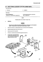
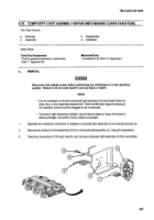
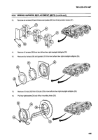
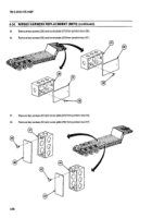
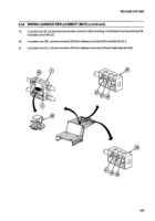
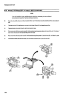
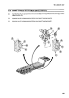
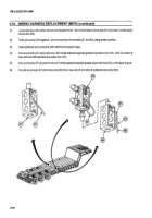
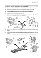
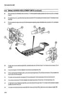
Remove six screws (1) from voltage reduction box (2).
2.
Remove box cover (3) from voltage reduction box (2).
3.
Remove black terminal wire screw (4) and 54-foot black circuit wire (5) from junction block (6).
2
10 0
0
5
4
4-63
Back to Top

