TM-5-2330-378-14-P - Page 194 of 524
TM 5-2330-378-14&P
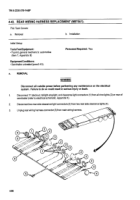
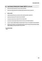
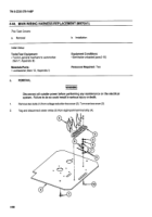
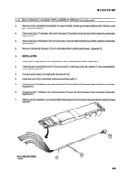
4-48. SLACK ADJUSTER REPLACEMENT.
ThisTaskCovers:
a.
Removal
b.
Installation
Initial Setup:
Tools/Test
Equipment:
Equipment
Conditions:
- Common
no. 1 tool set (item 6, Appendix
B)
- Brakes released (referto operators
manual
for truck tractor).
Materials/Parts:
- Wheels chocked (pare 2-10).
• Rag (item 15, Appendix F)
• Retaining ring (item 26, Appendix 1)
a.
REMOVAL
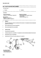
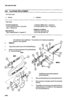
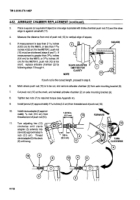
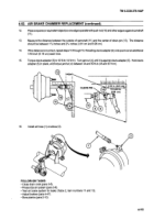
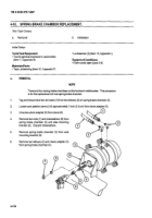
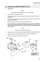
1. Remove two cotter pins (1), link pin (2), and clevis pin(3) from clevis (4). Turn adjustment nut (5) and rotate slack
adjuster (6) out of clevis (4).
2.
Remove retaining ring (7) from end of camshaft (8).
3.
Remove slack adjuster (6)from camshaft (8).
b. INSTALLATION
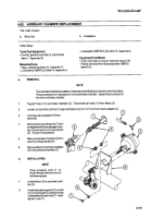
1. Clean splines (9) of camshaft (8).
2.
Install slack adjuster (6) on camshaft (8). Turn adjustment nut (5) and rotate slack adjuster (6) into clevis (4).
3.
Install retaining ring (7) on camshaft (8).
4.
Install clevis pin (3), link pin (2), and two cotter pins (1) on clevis (4).
8
9
2
6
4
3
6
FOLLOW-ONTASKS:
• Adjust brakes (pare 4-47).
• Unchock wheels (para 2-8).
4-106
Back to Top

