TM-5-2330-378-14-P - Page 203 of 524
TM 5-2330-378-14&P
4-53. SPRINGBRAKECHAMBERREPLACEMENT(continued).
b.
INSTALLATION
NOTE
Wrap threaded ends of all brass fittings with two turns of antiseizing tape.
1
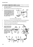
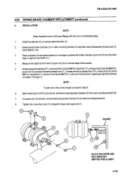
Install two elbows (2) on spring brake chamber (3).
2.
Install spring brake chamber (3) on axle mounting bracket (9) using two new lockwashers (8) and nuts (7).
Hand-tighten
nuts.
3.
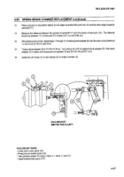
Place a square (or equivalent object) so oneedge is parallelwith brake chamberpush rod (10) andtheother
edge is against camshaft (11).
4.
Measure the distance from end of push rod (110)to vertical edge of the square.
5.
If measurement
is lessthan
21'/16
inches
(6.83 cm)forthe
M870
or lessthan
1II/le inches
(4.92 cm)forthe
M870AI,
push rod (10) must be shortened (steps 6 and 7). If measurement
is greater than 3
25/32
inches (9.6 cm) for the
M870 or more than 3
15/16
inches (10 cm)forthe
M870Al
, push rod (1O)istooshort;
replace spring brake chamber
(3) (steps 1 through 4).
NOTE
If push rod is the correct length, proceed to step 8.
6.
Mark where push rod (10) is to be cut, and remove spring brake chamber (3) from axle mounting bracket (9).
7.
Cut push rod (10) at mark, and reinstall spring brake chamber (3) on axle mounting bracket (9).
8.
Tighten two mounting nuts (7) to required torque (see appendix H).
3
SQUARE
3
1-15116In.
9
(4.92
CM) -
10
8
7
11
SLACK
ADJUSTER
AND
AXLE
BRACKET
OMITTED
FOR
CLARITY
4-115
Back to Top

