TM-5-2330-378-14-P - Page 201 of 524
TIVI
5-2330-378-14&P
4-52.
AIR BRAKECHAMBERREPLACEMENT
(continued).
12.
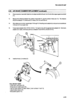
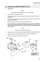
Placeasquare
(orequ ivalent object) so one edge isparallelwith
push rod (10)and otheredge
is against camshaft
(11).
13.
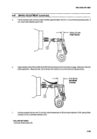
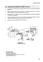
Measure the distance between the outside of camshaft (111)and the center of clevis pin (13). The distance
should be between
11/2
inches and 21/4inches (3.81 cm and 6.98 cm).
14.
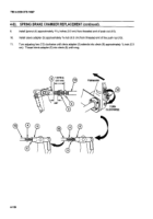
If the distance is incorrect, repeatsteps
10 through 13, threading clevis adapter(5)
onto push rod an additional
1/16 inch (0.16 cm) each time.
15.
Torque clevis adapter (5)to 10 ft-lb (14 N-m). Turn jam nut (4) until it is against clevis adapter (5). Holdclevis
adapter (5) in place, and torque jam nut (4) between 34 and 50 ft-Ib (45 and 67 N-m).
13
CLEVIS PIN
1-1/2 in. (3.81 cm
14
TO 2-3/4 In.
(6.9 cm)
10
16.
Install air hose (1) on elbow (3).
3
FOLLOW-ON TASKS:
• Close drain cock (para 3-8).
• Pressurize air system (para 3-8).
• Test air brake system for leaks (Table 2, item numbers 11 and 13).
• Adjust brakes (para 4-47).
• Stow planks (para 2-10).
4-113
Back to Top

