TM-5-2330-378-14-P - Page 321 of 524
TIVI5-2330-378-14&P
5-26.
RADIUSRODSCREWANDENDSREPLACEMENTANDADJUSTMENT,ANDAXLE
BRACKETREPLACEMENT
(M870)(continued).
3.
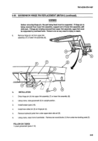
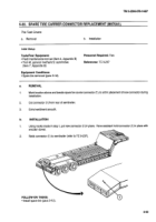
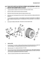
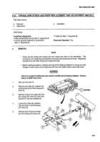
Loosen two bolts (12), washers (13), and nuts (14) in two radius rod ends (7 and 8).
4@
Remove two radius rod ends (7 and 8) from radius rod screw (9).
5.
Remove two mounts (115)and liners (116)f rom two radius rod ends (7 and 8).
6.
Remove two nuts (17) and washers (18) from U-bolt (119). Remove U-bolt (19) from middle axle (20) and axle
bracket (111).
7.
To aid in placement of axle bracket (11) during installation, mark location of axle bracket (11) on middle axle
(20). Cut weldment holding axle bracket (11) on middle axle (20). Remove axle bracket (111)from middle axle
(20).
8.
Grind weld off middle axle (20) surface. Be careful not to remove location marks.
17
18
14
9
16
15
13
7
11
19
21
21
15
16
12
8
20
b.
INSTALLATION
1.
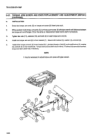
Put axle bracket (111)in position on middle axle (20) according to marks made during removal.
Install U-bolt
It 9) on axle bracket (11) and middle axle (20) and secure with two washers (18) and nuts (17).
2.
Weld axle bracket (111)to middle axle (20) (refer to TC 9-237).
3.
Screw two radius rod ends (7 and 8) onto radius rod screw (9), three turns each. While assistant holds radius
rod ends (7 and 8), turn radius rod screw (9) with pipe wrench until distance between two radius rod end flanges
(21) is the same as measurement
taken before start of procedure.
4.
Install two mounts (15) and liners (16) in two radius rod ends (7 and 8)
5-59
Back to Top

