TM-5-2330-378-14-P - Page 318 of 524
TM 5-2330-378-14&P
5-25. SPRINGASSEMBLYAND BOTTOMPLATEREPLACEMENT
(M870A1).
ThisTaskCovers:
a.
Removal
b.
Installation
Initial Setup:
Toolsrrest Equipment:
Equipment Conditions:
- Field maintenance tool set (item 4, Appendix B)
Middle axle tire and wheel assembly removed
*Tool kit, general mechanic's:
automotive
(para 3-10).
(item 7, Appendix B)
Trestle (3) (item 1, Appendix B)
Materials/Parts:
* Self-locking nut (Item 33, Appendix 1)
a.
REMOVAL
I
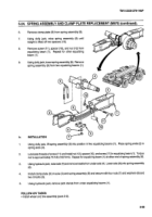
Place hydraulic jack under end of one equalizing beam (1), close to spring end (2). Lift equalizing beam (1)
approximately
three inches from normal position.
2.
Place trestle under equalizing
beam (1), just behind spring slot (3).
Remove hydraulic jack from under
equalizing beam (1).
3.
Repeat steps 1 and 2 for equalizing beam (1) at other spring end (2).
4.
Using hydraulic jack, lift middle axle (4). Place trestle under axle (4) and remove hydraulic jack.
5.
Remove two U-bolts (5) and four washers (6) and nuts (7) from spring assembly (8) and axle (4).
6.
Remove bottom plate (9) from spring assembly (8).
7.
Using dolly jack, raise spring assembly (8).
8.
Remove keeper bolt (10) and self-locking nut (11) from equalizing beam (1). Repeat for other equalizing beam
(1) at other end of spring assembly (8). Discard self-locking nut.
9.
Using dolly jack, lower spring assembly (8) and remove spring assembly (8) from semitrailer.
b.
INSTALLATION
1.
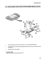
Using dolly jack, lift spring assembly (8) into position in both equalizing beams (1). Place spring ends (2) in
spring slots (3).
2.
Lubricate threads of keeper bolt (10) and install new self-locking nut (11) and keeper bolt (10) in equalizing
beam (1). Torque self-locking nut between 73 and 95 ft-lb (99 and 132 Nem). Repeat for equalizing beam
(1) at other end of spring assembly (8).
5-56
Back to Top

