TM-5-2350-377-13-P - Page 76 of 404
ELECTRICAL SYSTEM - Continued
STEP
1.
Check for ground continuity.
a.
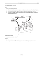
Disconnect control box power harness (Figure 1, Item 4) from control box (Figure 1, Item 2).
b.
Check for ground continuity from socket E (Figure 1, Item 1) to ground (Figure 1, Item 3) behind
instrument panel.
3
T00401HBF
2
4
1
5
Figure 1.
Control Box Power Harness.
CONDITION/INDICATION
Is continuity present?
DECISION
YES - If continuity is indicated, go to Step (2).
NO - If an open circuit is indicated, replace control box wiring harness (WP
0027). Verify that problem is solved.
STEP
2.
Check control box power wiring harness for a minimum of 24 VDC at socket C.
a.
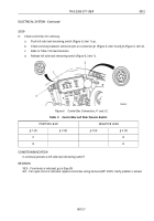
Using volt meter with negative lead in socket E (Figure 1, Item 1) and positive lead in socket C
(Figure
1,
Item
5), turn on master switch.
b.
Turn master switch off.
CONDITION/INDICATION
Are 24 VDC present at socket C?
TM 5-2350-377-13&P
0012
0012-2
Back to Top


