TM-5-3805-254-14-P-2 - Page 196 of 894
TRUCK SERVICE MANUAL
BRAKES-AIR
2.
Examine the diaphragm.
If any signs of damage or
deterioration are evident, replace the diaphragm.
When
one diaphragm requires replacement, it is good practice
to replace all of the brake chamber diaphragms in the
system while the vehicle is out of service.
Brake
chamber diaphragms must be replaced every 50, 000
miles or at least once a year, regardless of condition.
3.
Inspect push rod, spring and spring retainer.
If parts.
are damaged, they should be replaced.
Check return
springs.
If a load scale is available, compare their
tension with new spring.
Matching an old spring with a
new spring will indicate the condition of the old part.
4.
Check the condition of the non-pressure plate.
If the
clamping flanges on the plates are dented or damaged,
replace the plates.
Reassemble
1.
Install nuts (10) on mounting studs and clamp non-
pressure plate (8) in vise with inside of plate facing up.
2.
Install spring (6) in spring retainer (5).
3.
Install push rod assembly in body, press the assembly
down (brake applied position) to compress the spring
and use vise grip pliers on the outside of the push rod to
hold the spring compressed.
4.
Install diaphragm (3) in pressure plate (4).
5.
Position brake chamber plates matching up etch
marks made prior to disassembly.
6.
Install clamp (7) with bolts and nuts and tighten nuts
to 150 in. lbs.
torque.
Remove vice grip pliers.
7.
Install lock nut (11), yoke (14), pin (13) and cotter pins
(12).
8.
Assemble yoke and lock nut to push rod.
Test
To check for leaks, coat brake chamber around clamp
with soapsuds and apply air pressure to port in pressure
plate (4).
No leakage allowed.
Preventive Maintenance
Every month or every 2, 000 miles the brake chamber
push rod travel should be checked.
Push rod travel
should be kept at a minimum without brakes dragging.
Excessive travel of the brake chamber push rod shortens
the life of the diaphragm.
Over travel also slows braking
response.
Every year or every 50, 000 miles the brake chambers
should be disassembled and cleaned.
New diaphragms
must be installed. Be sure to use the correct diaphragm
return springs when reassembling the chamber or
uneven braking may result.
Adjustment
After the brake chamber is installed, the brakes must be
adjusted and checks made to be sure the linkage does
not bind.
Adjustment of the push rod length may be
accomplished by altering the location of the yoke.
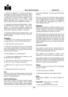
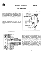
With brakes released, the angle formed by the push rod
and slack adjuster must be greater than 900, and all
slack adjusters should be set at the same angle.
With
the brakes applied, after being. adjusted, this angle
should still be greater than 90°.
In other words, the slack
adjuster should not go "over center" when the brakes are
applied (Fig. 7).
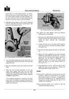
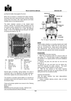
SLACK ADJUSTERS
Slack adjusters provide method of adjusting brakes to
compensate for brake lining wear, and also serve as a
lever during braking operation, (Fig. 20).
Slack adjusters were designed to conform to the
development of heavy-duty two-shoe foundation brakes.
During brake operation, the entire slack adjuster rotates
bodily with the camshaft. When adjusting the brakes, the
worm moves the gear so as to change the position of the
lever arms in relation to the brake camshaft.
Remove
1.
Remove cotter key and clevis pin from slack adjuster
and push rod clevis.
2.
Remove snap ring from camshaft.
3.
Slide slack adjuster from end of brake camshaft.
Install
Slack adjuster installation is the reverse procedure for
removal.
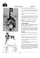
Disassemble
Refer to Fig.
21 for numbers
in parenthesis
1. Clean all grease and dirt from the outside
192
Back to Top


