TM-5-3805-254-14-P-2 - Page 319 of 894
TRUCK SERVICE MANUAL
ENGINE
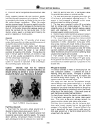
Lubricating oil is drawn from the pan, through a suction
tube, by the lubricating oil pump, Fig.
5-13, then
transferred from the suction cavity by the pump gears
into the pressure cavity.
Lubricating oil passes from the pump into the block, then
across the front of the block by means of an internal oil
passage and enters the cooler support.
Oil is routed out
of the cooler support and into the cooler housing,
passing through the cooler housing.
(The oil cooler is a
counterflow tube-and-shell type heat exchanger, with oil
passing from front to rear through the shell and coolant
water passing from rear to front through the tubes.) Oil
exits the cooler housing and passes into the cooler
cover, then enters the "rifle drilling" at the bottom rear of
the cooler housing and flows forward into the filter head.
Lubricating oil flowing into the filter shell from the filter
head enters outside the filter element and passes
through the element from outside to inside.
Filtered
lubricating oil then re-enters the filter head and flows
through rifle drilling in the bottom of the cooler housing,
then flows forward out of the cooler housing and into the
cooler
support
where
the
flow
divides.
Filtered and cooled lubricating oil re-enters the block
from the cooler support and is transferred internally back
across the front of the block through a drilled oil transfer
passage to the head of the main rifle drilling.
Accessory
drive lubrication is supplied from the transfer passage
out the front of the block and into the gear cover on the
exhaust side of the engine, then across the front of the
engine through a tube in the gear cover.
The flow path
then splits, part being routed to the accessory drive
bushing in the gear cover and the rest being routed to
the air compressor.
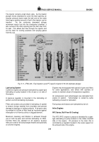
Piston-cooling is supplied from the transfer passage
leading to the head of the main rifle drilling.
An
intersecting drilling allows flow to the piston-cooling rifle
which extends from the front to the rear of the block on
the exhaust side of the engine.
Six piston-cooling
nozzles inserted from the outside of the block direct a
spray of lubricating oil from the piston-cooling rifle to the
bottom of each piston.
Lubricating oil entering the main rifle is routed by means
of drilled passages and pipes to the main bearings, rod
bearings, piston pin bushings, camshaft bushings, cam
follower shafts and levers, rocker box shafts and rocker
arms, etc. then returns to the oil pan.
Cooling System
Water is circulated by a centrifugal water pump mounted
either in or on the front of the engine belt driven from the
accessory drive or crankshaft.
Water circulates around wet-type cylinder liners, through
the cylinder heads and around injector sleeves. Injector
sleeves, in which injectors are mounted, are designed for
fast dissipation of heat.
The engine has a thermostat to
control engine operating temperature.
Engine coolant is
cooled by a radiator and fan or a heat exchanger.
The Fleetguard D C A Water Filter is standard on
Cummins Engines.
The filter by-passes a small amount
of coolant from the system via a filtering and treating
element which must be replaced periodically.
Air System
The diesel engine requires hundreds of gallons of air for
every gallon of fuel that burns.
For the engine to operate
efficiently, it must breathe freely, intake and exhaust
systems must not be restricted.
The intake air should always be routed through an air
cleaner.
The cleaner may be mounted on engine or
equipment and may.
be either oil bath, paper element of
composite type depending upon engine application.
Air
is routed from air cleaner directly to intake air manifold or
turbocharger.
Turbocharger
The turbocharger forces additional air into combustion
chambers so engine can burn more fuel and develop
more horsepower than if it were naturally aspirated.
In some cases the turbocharger is used for the engine to
retain efficiency (balanced fuel to air ratio) at altitude
above sea level.
The turbocharger consists of a turbine wheel and.
a
centrifugal blower, or compressor wheel, separately
encased but mounted on and rotating with a common
shaft.
The power to drive turbine wheel - which in turn drives
the compressor - is obtained from energy of engine
exhaust gases.
Rotating speed of the turbine changes
as the energy level of gas changes; therefore, the engine
is supplied with enough air to burn fuel for its load
requirements.
The turbocharger is lubricated and cooled by engine
lubricating oil.
315
Back to Top

