TM-5-3805-254-14-P-2 - Page 585 of 894
MOTOR
TRUCK SERVICE MANUAL
INSTRUMENTS
Electrical current supplied by the battery travels
through the ignition switch and enters the gauge at point
A (see Fig. 26).
From point A two possible paths exist to
complete the circuit to ground.
The current can flow
through the series connection of Coil 1, Coil 2, and the
calibrating resistor to ground; or it can travel through Coil
3 to the sender.
Since current will travel through the path
of least resistance, the flow path is determined by the
resistance of the sender as follows.
When the oil is cold, the sender’s resistance is high.
The current will, therefore, flow through Coil 1, Coil 2 and
the calibrating resistor to ground, which offers less
resistance than the sender path.
A small amount of the
current, however, follows the path through Coil 3 and the
sender.
(When current flows through a coil, a magnetic
field is developed around the coil.) Since Coils 1 and 3
are oppositely-wound, their resulting magnetic fields
oppose each other.
The remaining field around Coil 2
has an attraction for the magnet.
Since the magnet is on
the same spindle as the indicating pointer, the spindle
rotates toward the colder scale reading corresponding to
the oil temperature.
When the oil is hot, the sender’s resistance is low.
Thus, the majority of the current will flow through Coil 3
and the sender.
The remaining current will travel the
alternate path and create weak magnetic fields around
Coils 1 and 2.
The magnetic field around Coil 3
dominates the attraction for the magnet.
This field
rotates the pointer to the higher temperature scale
reading corresponding to the oil temperature.
Various combinations of current flow divided
between the two alternate paths result from changes in
the sender’s resistance.
The magnetic fields around the
coils in each respective case position the pointer at the
appropriate scale reading.
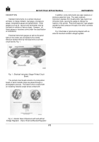
The calibrating resistor connects the ground terminal
with the tie-in terminal, Fig. 27.
The ground terminal is tin coated for identification.
This terminal grounds the gauge to the housing or cover.
The housing is grounded to the chassis through the
mounting studs.
The sender terminal is the first terminal clockwise
from the ground terminal (when viewed from the back
side).
The ignition terminal is directly opposite from the
sender terminal.
To determine faulty component parts, proceed as
follows:
1.
Disconnect sender wire at sender unit (point A), Fig.
27.
2.
Connect one lead of Fastestor to sender wire and
the other lead to a good ground.
3.
Set Fastestor left-hand knob at "120" and right-hand
knob at "0.
" Turn ignition switch "on.
" Gauge
should read approximately 170°F.
4.
Turn Fastestor left-hand knob to "30" and right-hand
knob to "3."
Gauge should read approximately
300
°
F.
Turn ignition switch "off." Reconnect sender
wire to sender unit (point A).
Fig. 27.
Oil Temperature Gauge Circuit
578
Back to Top


