TM-5-3805-254-14-P-2 - Page 580 of 894
INSTRUMENTS
MOTOR
TRUCK SERVICE MANUAL
(lower end first) through the lubricant back into the
casing, leaving only a thin coating on the core.
When
lubricating the core, leave four inches free of lubricant to
prevent lubricant entering the instrument head.
Speedometer and Tachometer Heads
Some speedometer and tachometer heads include
provision for lubrication.
Examine the tachometer head,
and where lubricant openings are provided in the rear of
the head at the cable take-off, lubricate as follows.
Inject 1 to 2 drops of "3 in 1" oil every 15, 000 to 20,
000 miles of operation.
Under severe service or
extremely hot climate lubricate more often.
AC MANUFACTURED INSTRUMENT GAUGES
The water temperature, oil pressure and air pressure
gauges are mechanical with Bourdon tube type
construction.
The electrical gauges are the fuel level and
battery-generating system indicator (voltmeter) utilizing
the air core type construction.
All gauges have direct
lighting.
Gauge Operation and Servicing
Water Temperature Gauge:
The mechanical temperature gauge operates on a
Bourdon tube motion which is transmitted to a pointer
through a sector and pinion gear linkage.
The
temperature gauge, unlike the mechanical air and oil
pressure gauges, is a hermetically sealed unit consisting
of a gauge, a capillary tube and a temperature bulb
which is filled with ether, Fig. 19.
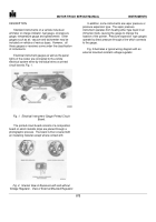
Fig. 19.
Water Temperature Gauge
When the bulb temperature increases as a result of
engine operation, the contained ether vaporizes, exerting
a vapor pressure on the inlet of the Bourdon tube, Fig.
20.
The pressure causes the tube to straighten out.
The
indicator point, which is attached to the Bourdon tube by
the gear linkage, then rotates across the dial in an
upscale direction.
The gauge achieves a temperature scale, reading
corresponding to the engine operating temperature.
When the engine is shut off, the ether vapor condenses
and settles in the bulb as the engine cools.
General gauge operation can be checked by
removing the sending bulb from the engine block.
Submerge the bulb in cold water; the gauge should
descend downscale.
Submerge the bulb in boiling water;
the gauge should ascend upscale.
Because of the
construction of the gauge, if either of these tests proves
unsatisfactory, replace the temperature gauge assembly.
Oil Pressure Gauge:
During engine operation oil is pumped throughout
the lubricating channels of the engine block.
The level of
pressure in the system depends upon the temperature,
oil supply and the condition of the system itself.
The oil pressure gauge measures the system’s oil
pressure.
The gauge operates with a Bourdon tube
motion transmitted through a pointer by way of a sector
and pinion gear linkage, Fig. 20.
Fig. 20.
Oil Pressure Gauge
575
Back to Top

