TM-5-3805-254-14-P-2 - Page 581 of 894
MOTOR
TRUCK SERVICE MANUAL
INSTRUMENTS
During engine operation oil enters the connecting
tube and exerts a pressure on the inlet of the Bourdon
tube.
As the oil pressure increases, the Bourdon tube
mechanism within the oil gauge tends to straighten.
The
indicator pointer, which is attached to the Bourdon tube
by the linkage, then rotates across the face of the dial in
the upscale direction.
When the oil pressure decreases,
the Bourdon tube relaxes and the pointer rotates in the
downscale direction.
A steadily applied oil pressure
holds the Bourdon tube and the pointer at a fixed scale
reading corresponding to the applied pressure.
1.
If the gauge is reading high:
a.
Disconnect the gauge from the system.
b.
If pointer does not return to the lowest scale
reading (for instance, the pointer stays at 40 psi),
the Bourdon tube has been damaged.
Service
by replacing with new gauge,
2.
If the gauge is reading low:
a.
Examine the connecting tube for dirt restricting
the oil from entering the Bourdon tube.
b.
If connections and tubing are secure and free
from dirt, the gauge is damaged.
Service by
replacing with new gauge.
NOTE:
Be certain
that engine oil pump is delivering correct
pressure before discarding gauge.
Air Pressure Gauge:
The mechanical air pressure gauge operates on the
Bourdon tube principle as does the mechanical oil
pressure gauge.
The air pressure gauge, as is implied,
uses air as a pressure source rather than oil.
For a
description of the operation, refer to the mechanical oil
pressure gauge.
For servicing procedure, refer to the mechanical oil
pressure gauge.
Battery- Generating System Indicator Gauge:
The battery-generating system indicator gauge
indicates the condition of the battery, alternator and the
voltage regulator.
The gauge is divided into two sections, one marked
"BATT" (battery), the other marked "GEN" (generating
system).
Before starting the engine with key switch off, the
gauge will show the condition of the battery.
The battery
section of the gauge is subdivided into three colored
segments:
GREEN - a well-charged battery
YELLOW - a low battery charge
RED - a very low battery charge
With the engine running at operating speeds the
gauge will show the condition of the generating system.
The generating section of the gauge is divided into two
colored segments:
GREEN - generating system working properly
RED - voltage output too high
Constant reading in either RED area indicates that a
complete check of the battery and generating system
should be made.
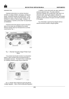
Terminal identification is as follows, Fig. 21:
1.
The ground terminal is tin plated.
2.
The ignition terminal is the first terminal
counterclockwise from the ground terminal (looking
at back of gauge).
3.
The ignition terminal and the tie-in terminal are
copper colored and are joined by a calibrating
resistor.
Fig. 21.
Battery-Generating System Indicator Gauge
Connect a known voltage source (battery) to the
voltmeter terminals.
The voltmeter should indicate the voltage supplied by
the source (battery) ± .5 volt.
If this test proves UNSATISFACTORY, service the
voltmeter by replacement.
If test is SATISFACTORY, the problem is in the
wiring; CHECK CAREFULLY.
576
Back to Top

