TM-5-3990-263-13-P - Page 478 of 728
INSTALLATION - Continued
29
27
28
28
27
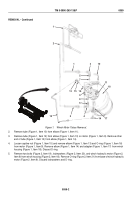
22
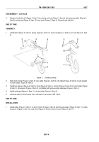
Figure 7.
Pivot Plates Installation.
4.
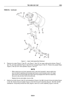
Install six screws (Figure 8, Item 23), nuts (Figure 8, Item 24), two upper cable guide retainers (Figure 8, Item
18), and roller assembly (Figure 8, Item 25) on carriage (Figure 8, Item 21). Install two grease fittings (Figure
8, Item 26) on ends of roller assembly (Figure 8, Item 25).
TM 5-3990-263-13&P
0058
0058-8
Back to Top

