TM-5-5420-202-10 - Page 372 of 535
0055
TM 5-5420-202-10
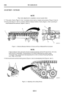
18.Move vehicle until end connector (Figure 8, Item 2) is located back at 9 o’clock position in relation to
compensating idler wheel (Figure 8, Item 3).
19.Repeat steps 12 through 14.
20.Tighten inner and outer connector bolts. Refer to WP 0049.
21.Start engine. Refer to WP 0015.
22.Move vehicle until center guide (Figure 8, Item 5) is located between compensating idler wheel (Figure 8, Item 3)
and number one roadwheel (Figure 8, Item 4).
23.Repeat steps 12 through 14.
24.Tighten center guide bolt (Figure 8, Item 1) and adjust track tension. Refer to WP 0056.
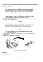
Figure 8.
Center Guide Nut.
END OF TASK
ENDOFWORKPACKAGE
0055-6
ASSEMBLY - CONTINUED
Back to Top


